Hi,
I got an old, furniture-style tube radio Philips FX651A (service manual attached).
I have a fair bit of experience in tube guitar amps, but none in old tube radios, TVs, etc...
The idea is to salvage as much parts as possible and transform it into a small SE guitar amp.
As I can understand, there is two SE OT, probably one for the bass-mid speaker, the other for the treble speaker ?
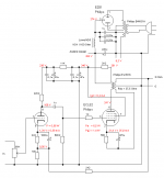
On the schematic, the connection of the top OT is pretty straightforward, nothing unusual there.
But I don't understand the connection of the bottom OT, the +++ and ++ connections. Could you explain, and how to connect it, if possible, in a regular way ?
Also, the bottom OT is bigger in size, probably different bandwidth ?
Speakers and PT are missing, and there is no information on speaker impedance or whatsoever, same for PSU voltages.
Any information would be very welcome.
Thanks !
I got an old, furniture-style tube radio Philips FX651A (service manual attached).
I have a fair bit of experience in tube guitar amps, but none in old tube radios, TVs, etc...
The idea is to salvage as much parts as possible and transform it into a small SE guitar amp.
As I can understand, there is two SE OT, probably one for the bass-mid speaker, the other for the treble speaker ?
On the schematic, the connection of the top OT is pretty straightforward, nothing unusual there.
But I don't understand the connection of the bottom OT, the +++ and ++ connections. Could you explain, and how to connect it, if possible, in a regular way ?
Also, the bottom OT is bigger in size, probably different bandwidth ?
Speakers and PT are missing, and there is no information on speaker impedance or whatsoever, same for PSU voltages.
Any information would be very welcome.
Thanks !
Attachments
I stand corrected, speakers impedances are listed at the top of the service manual. But there is 3 speakers listed, but only two visible on the plan.
The bottom OPT has a anti-hum and/or, as some explain, a pre-magnetizing provision. S37 is the 'normal' part of the primary. The current for the rest of the radio (except the anode currents of the two EL84's) flows (in the opposite direction of the anode current of the lower EL84) through S38, comes out as B++, than flows through R1 to 'become' B+ for the rest of the radio.
Very interesting, thanks.
So this pre-magnetizing provision act kind of like a choke, combined with some sort of hum cancelation ? Could you elaborate please ? I can't find informations about it.
Is it worth including it in the design of a guitar SE ?
About the voltages, as I can see, the B+ at the EM80 is 213V. Not knowing the preamp tubes types, is it safe to assume the B++ was at about 240-250V as a rough estimate ?
Yes, I think your 240-250 V is a good estimate. Maybe it is even a bit higher.
The current flowing through S38 is pretty high (rough estimate: 50 mA). But I think that S38 has much fewer windings than S37 so that's why I think that the possible pre-magnetizing effect (in a opposite direction to the anode current through S37) will not be substantial. I understood that it worked mainly as a hum-suppressor, in which the ripple flowing through S37 partly cancels the ripple flowing through S38. But that's about as deep as my knowledge goes. I don't really know a site/source in English where it is explained in more detail.
I don't know if it is a good idea to use S38 in a guitar amplifier because the current through S38 will be much lower than in the radio. Some time ago when I knew less about this stuff I did use an OPT with such a anti-hum provision in an SE amplifier with ECL82's. It worked fine but the OPT's were from tape recorders in which the current to the rest of the tubes was much lower than in your radio. But if you decouple good enough after S38 it will probably work anyway.
I just noticed a mistake in the schematic of your radio. R61 at the screen grid of the upper EL84 can't be 820K, so probably is 820, like R56 at the lower EL84.
Attachments
Last edited:
Ok, I'll experiment it in due time.
Well seen for the mistake, it seems unlikely indeed.
Thank you !
Well seen for the mistake, it seems unlikely indeed.
Thank you !