Hi DIYers,
I am working on an unique directed coupled 300B amp.
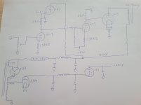
All triodes are common cathode configuration.
2 stage 6SN7 amplification, first stage 6SN7 and second stage are capacitance coupled, second stage 6SN7 and 300B are direct coupled.
I don't use high watt resistance to raise cathode voltage of 300B, instead I use negative voltage supply for second stage 6SN7.
I use 866A tube in B+ and EY84 in B-
All parts and chassis are ready for assembly.
Happy to hear your comments!
I am working on an unique directed coupled 300B amp.
All triodes are common cathode configuration.
2 stage 6SN7 amplification, first stage 6SN7 and second stage are capacitance coupled, second stage 6SN7 and 300B are direct coupled.
I don't use high watt resistance to raise cathode voltage of 300B, instead I use negative voltage supply for second stage 6SN7.
I use 866A tube in B+ and EY84 in B-
All parts and chassis are ready for assembly.
Happy to hear your comments!
The parts and chassis are ready for assembly so you must have a schematic for us?
If the power supply is going to be a full-wave circuit, you need 2.5 V / 10 A for the filaments of the 866A's. Since a pair of 866A's can provide 500 mA, it is a beefy power supply for 2 x 300B (which will take somewhere between 140 and 200 mA).
If the power supply is going to be a full-wave circuit, you need 2.5 V / 10 A for the filaments of the 866A's. Since a pair of 866A's can provide 500 mA, it is a beefy power supply for 2 x 300B (which will take somewhere between 140 and 200 mA).
866 being a Mercury Vapor Rectifier needs time to warm up. I presume you are using this to insure your negative supply is up first. You might want to consider a lockout from the negative supply for the positive supply in the unlikely event the negative supply does not come up.
Just be careful to shield the 866. The UV is dangerous. Particularly for vision.
Just be careful to shield the 866. The UV is dangerous. Particularly for vision.
Hi DIYers,
I am working on an unique directed coupled 300B amp.
All triodes are common cathode configuration.
2 stage 6SN7 amplification, first stage 6SN7 and second stage are capacitance coupled, second stage 6SN7 and 300B are direct coupled.
I don't use high watt resistance to raise cathode voltage of 300B, instead I use negative voltage supply for second stage 6SN7.
I use 866A tube in B+ and EY84 in B-
All parts and chassis are ready for assembly.
Happy to hear your comments!
Differential stages are usually found in DC coupled amplifiers to cancel drift of the OP.. The negative supply should be limited to prevent H-K failure of the 6SN7 driver. A good number is -150V, easily got using a common VR tube. That way the OP of the 300B doesn't move too far.🙂
In the usual hookup some signal is lost. But by using selected NE51H or a 991 Neon regulator in the coupling network that can be avoided. Google Philbrick Vacuum Tube Operational Amps for some good examples of how its done.
2 stage 6SN7 amplification, first stage 6SN7 and second stage are capacitance coupled, second stage 6SN7 and 300B are direct coupled.
I don't use high watt resistance to raise cathode voltage of 300B, instead I use negative voltage supply for second stage 6SN7.
Be aware that type 300B warms up much faster than type 6SN7, so at startup the 300Bs will have very large positive grid voltage. They may survive this if B+ is properly delayed (necessary for mercury poisoning rectifiers anyway) or they may complain.
Timing delays for the various power supplies need to be robust with all possible mains power offs, from overnight down to breif line transients. Doable but not trivial.
Also, as JHS implies, the 300B's bias is going to be swinging wildly all over the place. Just more larfs.
All good fortunes,
Chris
Last edited:
Thank you for your reply.
I don't use full wave circuit so avoid 2.5V 10A winding.
I don't use full wave circuit so avoid 2.5V 10A winding.
The parts and chassis are ready for assembly so you must have a schematic for us?
If the power supply is going to be a full-wave circuit, you need 2.5 V / 10 A for the filaments of the 866A's. Since a pair of 866A's can provide 500 mA, it is a beefy power supply for 2 x 300B (which will take somewhere between 140 and 200 mA).
Thank you for your reply.
I add a 30 second relay on HT.
I will wear UV glasses.
I add a 30 second relay on HT.
I will wear UV glasses.
866 being a Mercury Vapor Rectifier needs time to warm up. I presume you are using this to insure your negative supply is up first. You might want to consider a lockout from the negative supply for the positive supply in the unlikely event the negative supply does not come up.
Just be careful to shield the 866. The UV is dangerous. Particularly for vision.
Thank you for your reply.
It will have a dedicated 6.3V winding for -280V 6SN7 cathode.
I choose -280V for 6SN7 cathode to deliver enough swing of 300B grid.
I would like to preserve 2nd order harmonic of triode, neither different pair nor SRPP is applied.
I has crafted a SE 300B amp, left channel is common cathode and right channel is SRPP. Interesting to listen it.
Differential stages are usually found in DC coupled amplifiers to cancel drift of the OP.. The negative supply should be limited to prevent H-K failure of the 6SN7 driver. A good number is -150V, easily got using a common VR tube. That way the OP of the 300B doesn't move too far.🙂
In the usual hookup some signal is lost. But by using selected NE51H or a 991 Neon regulator in the coupling network that can be avoided. Google Philbrick Vacuum Tube Operational Amps for some good examples of how its done.
Last edited:
Thank you for your reply.
I add a 30 second relay between 500V winding and 866A anode.
I will consider some safety circuit on -280V supply.
I add a 30 second relay between 500V winding and 866A anode.
I will consider some safety circuit on -280V supply.
Be aware that type 300B warms up much faster than type 6SN7, so at startup the 300Bs will have very large positive grid voltage. They may survive this if B+ is properly delayed (necessary for mercury poisoning rectifiers anyway) or they may complain.
Timing delays for the various power supplies need to be robust with all possible mains power offs, from overnight down to breif line transients. Doable but not trivial.
Also, as JHS implies, the 300B's bias is going to be swinging wildly all over the place. Just more larfs.
All good fortunes,
Chris
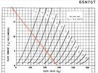
Assuming that the control grid voltage of the 300B will be something like - 100 V, I come to these calculations for the second stage:
Ia = V(Ra) / Ra = 100 / 15K = 6.7 mA
Bias = 0.0067 x 1780 = - 11.9 V
V(anode to cathode) = 280 - 100 - 11.9 = 168.1 V
Looking at the curves for the 6SN7 these numbers don't seem right. At Va = 168.1 V and Vg1 = - 11.9 V a 6SN7 would not pass any current at all.
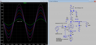
I thought that using large capacitors with voltage regulators could lead to oscillations, unless the voltage regulator has an additional ignition/start electrode (like for instance the ZZ1040 has).
I don't think that half-wave rectification for the 300B's is a wise choice for an amplifier like this because of the high ripple. Furthermore the power transformer should be able to pass a substantial amount of dc-current. What I am unsure about is the effect of 2 x half-wave rectification, in opposite directions, and with very unequal currents, from only one transformer winding.
Ia = V(Ra) / Ra = 100 / 15K = 6.7 mA
Bias = 0.0067 x 1780 = - 11.9 V
V(anode to cathode) = 280 - 100 - 11.9 = 168.1 V
Looking at the curves for the 6SN7 these numbers don't seem right. At Va = 168.1 V and Vg1 = - 11.9 V a 6SN7 would not pass any current at all.
I thought that using large capacitors with voltage regulators could lead to oscillations, unless the voltage regulator has an additional ignition/start electrode (like for instance the ZZ1040 has).
I don't think that half-wave rectification for the 300B's is a wise choice for an amplifier like this because of the high ripple. Furthermore the power transformer should be able to pass a substantial amount of dc-current. What I am unsure about is the effect of 2 x half-wave rectification, in opposite directions, and with very unequal currents, from only one transformer winding.
Last edited:
This is a fetish item, a modern extension of a fashion item. Some may blame modern culture, but I blame pandemic idleness.
All good fortune,
Chris
All good fortune,
Chris
Thank you for your reply.
Second stage 6SN7 cathode is around -270V, Ia is around 5mA.
Second stage 6SN7 cathode is around -270V, Ia is around 5mA.
Assuming that the control grid voltage of the 300B will be something like - 100 V, I come to these calculations for the second stage:
Ia = V(Ra) / Ra = 100 / 15K = 6.7 mA
Bias = 0.0067 x 1780 = - 11.9 V
V(anode to cathode) = 280 - 100 - 11.9 = 168.1 V
Looking at the curves for the 6SN7 these numbers don't seem right. At Va = 168.1 V and Vg1 = - 11.9 V a 6SN7 would not pass any current at all.
I thought that using large capacitors with voltage regulators could lead to oscillations, unless the voltage regulator has an additional ignition/start electrode (like for instance the ZZ1040 has).
I don't think that half-wave rectification for the 300B's is a wise choice for an amplifier like this because of the high ripple. Furthermore the power transformer should be able to pass a substantial amount of dc-current. What I am unsure about is the effect of 2 x half-wave rectification, in opposite directions, and with very unequal currents, from only one transformer winding.
Attachments
With Ia being around 5 mA, the voltage on the control grid of the 300B would be: 0.005 x 15K = - 75 V.
With B+ being 450 V and with Vg = - 75 V a 300B would pass way too much current. Even with a substantial voltage drop in the OPT the current would still be around 200 mA. The plate dissipation would be over 80 Watt.
This will ofcourse distroy your 300B's. That is why in post #11 I assumed Vg to be something like - 100 V. At Vg = - 100 V the 300B's would stay within their maximum ratings.
Additional:
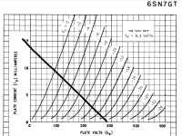
If Ia = 5 mA, than:
Va = - 75 V (= 0.005 x 15K)
Bias = - 8.9 V (= 0.005 x 1780)
V(anode to cathode) = 280 - 75 - 8.9 = 196.1 V
Looking at the curves, these numbers again don't add up. At Va = 196.1 V and Vg = - 8.9 V, the current would be something like 2 mA instead of 5 mA.
With B+ being 450 V and with Vg = - 75 V a 300B would pass way too much current. Even with a substantial voltage drop in the OPT the current would still be around 200 mA. The plate dissipation would be over 80 Watt.
This will ofcourse distroy your 300B's. That is why in post #11 I assumed Vg to be something like - 100 V. At Vg = - 100 V the 300B's would stay within their maximum ratings.
Additional:
If Ia = 5 mA, than:
Va = - 75 V (= 0.005 x 15K)
Bias = - 8.9 V (= 0.005 x 1780)
V(anode to cathode) = 280 - 75 - 8.9 = 196.1 V
Looking at the curves, these numbers again don't add up. At Va = 196.1 V and Vg = - 8.9 V, the current would be something like 2 mA instead of 5 mA.
Last edited:
Thank you for your great input.
I change plate load of 2nd stage 6SN7 from 15kohm to 20kohm, change cathode resister to 1.3kohm, to make 300B control grid approaching -100V
I change plate load of 2nd stage 6SN7 from 15kohm to 20kohm, change cathode resister to 1.3kohm, to make 300B control grid approaching -100V
With Ia being around 5 mA, the voltage on the control grid of the 300B would be: 0.005 x 15K = - 75 V.
With B+ being 450 V and with Vg = - 75 V a 300B would pass way too much current. Even with a substantial voltage drop in the OPT the current would still be around 200 mA. The plate dissipation would be over 80 Watt.
This will ofcourse distroy your 300B's.
Addition:
If Ia = 5 mA, than:
Va = - 75 V (= 0.005 x 15K)
Bias = - 8.9 V (= 0.005 x 1780)
V(anode to cathode) = 280 - 75 - 8.9 = 196.1 V
Looking at the curves, these numbers again don't add up. At Va = 196.1 V and Vg = - 8.9 V, the current would be something like 2 mA instead of 5 mA.
Last edited:
I did enough calculating by now. I think it would be good that you show us how you calculated the changes you now propose.
Each solution is very hazardous.
If the driver tube not working properly (not heated, failed, tube socket problem etc.) the power tube (without excessive protection) immediately would burning out (zero negative bias).
Instead of it try to use cathode or source follower, where the negative voltage on the grid protects the power tube.
- Home
- Amplifiers
- Tubes / Valves
- 6SN7 > 6SN7 > 300B , 6SN7 DC 300B