Hello all!
First time posting and recently joined.
What a fantastic resource this forum is.
Id like to introduce myself. James 32 from Yorkshire, UK.
Always had a fascination with hifi audio. Mostly due to being surrounded by good gear of my fathers.
Last year I completed a rebuild of a Armstrong based ECL86 stereo push-pull amplifier which I was very happy with after it was left in bits in the garage on my dads to do list. Anyway it is now in service and has left me wanting to build my own amplifier.
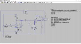
I have settled on 6L6GC SE amp and would like some input / verification my design is sound. I know simulation is not always perfect and might want some changes along the way. I have attached a LTspice simulation.
I think I have got the biasing correct. But my simulation is currently producing circa +/-30v to the 6L6GC control grid. The simulation suggests no clipping etc but seems excessive. Any thoughts?
The amp is likely to be powered with a 5U4GB rectifier, and looking at some Edcor power transformers and Edcor 5K to 8 Ohm 10w output transformers.
Look forward to hearing your thoughts and comments.
Many thanks
James
First time posting and recently joined.
What a fantastic resource this forum is.
Id like to introduce myself. James 32 from Yorkshire, UK.
Always had a fascination with hifi audio. Mostly due to being surrounded by good gear of my fathers.
Last year I completed a rebuild of a Armstrong based ECL86 stereo push-pull amplifier which I was very happy with after it was left in bits in the garage on my dads to do list. Anyway it is now in service and has left me wanting to build my own amplifier.
I have settled on 6L6GC SE amp and would like some input / verification my design is sound. I know simulation is not always perfect and might want some changes along the way. I have attached a LTspice simulation.
I think I have got the biasing correct. But my simulation is currently producing circa +/-30v to the 6L6GC control grid. The simulation suggests no clipping etc but seems excessive. Any thoughts?
The amp is likely to be powered with a 5U4GB rectifier, and looking at some Edcor power transformers and Edcor 5K to 8 Ohm 10w output transformers.
Look forward to hearing your thoughts and comments.
Many thanks
James
Attachments
I don't use LTspice so my comments/questions are only based on your schematic.
After C1 there should be a grid leak resistor (or a volume pot) to ground.
What is the planned impedance of the primary of the output transformer? Beside a primary impedance (for signal) the primary of an output transformer will also have a dc-resistance, so the plate voltage will be somewhat lower than B+.
Addition: I think that the gain in the first stage is too low to apply global negative feedback like in your schematic. The 6L6GC in triode mode needs about 20 V input signal for full power. The gain of the first stage is not even 20 (I estimate the gain to be something like 12), so there is not even enough gain to drive the 6L6GC to full power.
Last edited:
Thank you for the response. Yes there will be a volume pot before c1.
Transformer specs would be this is for a Edcor GXSE10-8-5K:
Wattage10W
Primary (input) Impedance 5K Ohms (5000 Ohms)
Primary (input) DCR 149 Ohms Primary (input)
Inductance 6H
Screen/Grid Tap 40% Secondary (output)
Impedance 8 Ohms Secondary (output)
DCR1.2 Ohms
I have rerun the sim, and added the 149 Ohm value to L1 which does indeed drop the plate voltage, and as such adjusted the value of R9 to 270Ohm targeting 25w disipation of the 6L6GC.
Last edited:
What is the planned impedance of the primary of the output transformer?
Seen from the schematic : inductance ratio of the output transformer is 6/0.0096=625 and 625 x 8 ohms = 5000 ohms.
Thank you for the response. Yes there will be a volume pot before c1.
To be sure: If you install a pot before C1 than you still need a grid leak resistor after C1 (so between C1 and the two control grids of the 6SN7) because the control grids should have a path for dc to ground (without it the control grids would 'float').
I was still busy with my addition in my frst post when you posted your reaction. Sorry for that.
Seen from the schematic : inductance ratio of the output transformer is 6/0.0096=625 and 625 x 8 ohms = 5000 ohms.
It's new to me that there is such a hard relation between the primary and secondary inductance. Thanks for that.
I think I have got the biasing correct. But my simulation is currently producing circa +/-30v to the 6L6GC control grid. The simulation suggests no clipping etc but seems excessive. Any thoughts?
The amp is likely to be powered with a 5U4GB rectifier, and looking at some Edcor power transformers and Edcor 5K to 8 Ohm 10w output transformers.
Look forward to hearing your thoughts and comments.
Many thanks
James
Any signal higher than the bias voltage will be clipped. If you carry a high bias voltage, depending on the plate voltage, you will hit the tube cutoff voltage (-) before you get the (+) signal up to the bias voltage. Your biasing now shows @ 80mA and I believe that is very close to the OPT transformer max current rating. Your plate voltage is the same as B+ and that won't happen because of voltage drop through the OPT. You need to start with the correct plate voltage you want and then work backward through the OPT and choke or B+ dropper resistance and the voltage drop of the rectifier, adding each drop, to arrive at the necessary PT HT starting voltage.
Last edited:
6SL7 will provide more gain; can give a reasonable input level with negative feedback. R1, R3 would change accordingly.
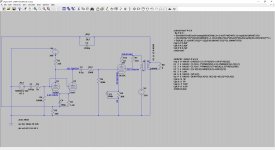
I have tweaked my sim as posted.
I have basically put a potential divider between the stages to trim the output of the 6SN7 to less than 20vpp to limit clipping.
A grid leak stopper also on the input as suggested.
Any other areas I have neglected?
I have basically put a potential divider between the stages to trim the output of the 6SN7 to less than 20vpp to limit clipping.
A grid leak stopper also on the input as suggested.
Any other areas I have neglected?
Attachments
If you mean Global native feedback, then the phase from OT output is reversed, GNFB should reduce the output level instead of increasing it. You can always compare both waveform if you're not sure, For NFB the output and input is same phase. How are going to decide the actual phase in the amp?
The potential divider makes the gain problem even worse (see my addition in post #2). If you want to apply global negative feedback you need more gain than the 6SN7 can supply. Even without the feedback, but with the potential divider, there is not enough gain to drive the 6L6GC to full power.
I have tweaked my sim as posted.
I have basically put a potential divider between the stages to trim the output of the 6SN7 to less than 20vpp to limit clipping.
A grid leak stopper also on the input as suggested.
Any other areas I have neglected?
I think you're trying to squeeze blood from a stone. With triode strapping and NFB you are trying to get max signal from the drivers to get some power. But you are running the paralleled drivers too cold. You're @ 3.5mA for both together. Typical Ip is around 9-10ma. for each plate. So your driver scheme is really off I think and you wouldn't add a 100k resistor in series with the output to try to restrict the signal level to the outputs. You would rebias and reset the driver plate voltage to get what you want for input sensitivity and gain. Triode strapping and FB is a hard balance to get right if you want any power at all. Are you OK with 1W? You really don't need parallel drivers. And, 20v p-p signal is 10v peak, way under the 6L6 bias point of 23v.
Last edited:
It's new to me that there is such a hard relation between the primary and secondary inductance. Thanks for that.
It derives from the turns ratio.
- Home
- Amplifiers
- Tubes / Valves
- New to the forum. Planning 6L6GC SE Amp