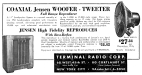
I came across a 1940s Jensen JHP-51, hoping to mate it with a JHP-52 I already had. These look almost the same, same cone, same spider, and both came with 500 ohm impedance matching transformers and coaxially mounted tweeters.
But then came the surprise: I measure the JHP-51 VC, has an 88 ohm DC resistance (guessing around 100 ohm impedance). And indeed, the transformer has a 2.25 turns ratio, resulting in the expected 500 ohm external connection. Out of curiosity I connected it up to a receiver with 8 ohm output and listened to it at low volume for a short time, and it works.
The JHP-52, the later model, has a more typical 8 ohm VC, mated with a 8 turns-ratio transformer, also resulting in the expected 500 ohm external connection.
The 500 ohm reflected impedance is not surprising, there are many examples (sounds like there were even some speakers with 500 ohm voice coils). But the 100 ohm voice coil was a surprise, and I don't see any other reference to such thing anywhere. Was it entirely a one-off, completely non-standard thing? Since I don't want to use the 500 ohm impedance, I will likely replace the coil with an 8 ohm one, to match the JHP-52.
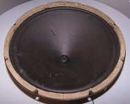
Update on the work. The original cone was in a bit rough shape with several tears, and some cracks and weak spots at the surround. Also the outer edge was damaged during the removal; it was glued to the frame with strong and hardened glue, very hard to remove. But most of the cone is in decent shape, the paper feels strong, and not brittle as many speakers of this age do. I got the tears and weak spots reinforced, including the edge, and now it looks/feels functional, though cosmetically not great looking. Attached are a before and couple of after pictures of the cone.
I am trying to decide whether to keep using this cone, or get a new one. Weber has some 15" paper cones that are close, but not perfect match; the depth is about 1/4 inches too short. I am tempted to keep using the old cone; note that the spider and the tinsel wires still attached, which I suppose is a plus. I guess I can decide to replace the cone at later point if the old does not work out. Thoughts?
I am trying to decide whether to keep using this cone, or get a new one. Weber has some 15" paper cones that are close, but not perfect match; the depth is about 1/4 inches too short. I am tempted to keep using the old cone; note that the spider and the tinsel wires still attached, which I suppose is a plus. I guess I can decide to replace the cone at later point if the old does not work out. Thoughts?
Attachments
Not sure what´s the point of getting such an old/vintage/Classic speaker and then *reconing* it ?????
Which voice coil will you use, just to begin with?
Any pictures of the old one?
Let alone the messing with an old, dry, frail cone; it will NOT sound like the original one by any means.
You are messing with the moving parts, which give a speaker its "voice", literally.
I would have left that as-is (besides patching obvious tears) and replaced the transformer with one having 8 ohm primary; transformers are far simpler, flatter, and easier to update.
Yes, that is the one. The younger sibling, the JHP-52 that has 8 ohm VC, can be seen in a lot more ads. And another sibling, the Western Electric / IPC LU-1004 that was made for movies seems to be in high regard.
I got the JHP-52 first, thinking of using it as guitar speaker. I mounted it in an ugly open back cab just to test it out. I hooked it up to a receiver, and wow... I changed my mind, it sounds very nice for listening to all kinds of music. So now I need to think about what to build for them. Although the 15" driver part by itself is not full range, it goes pretty high. I think it would work well with a two-way system crossed at 3-4k. They have stiff surround and low excursion, perhaps try them for OB?
I got the JHP-52 first, thinking of using it as guitar speaker. I mounted it in an ugly open back cab just to test it out. I hooked it up to a receiver, and wow... I changed my mind, it sounds very nice for listening to all kinds of music. So now I need to think about what to build for them. Although the 15" driver part by itself is not full range, it goes pretty high. I think it would work well with a two-way system crossed at 3-4k. They have stiff surround and low excursion, perhaps try them for OB?
Not sure what´s the point of getting such an old/vintage/Classic speaker and then *reconing* it ?????
Simply put: to give them second chance at life. One of them got spray painted by someone. You know, with the cheap black spray paint kind of thing. And not just the metal basket... the cone, the small and non-original HF driver, the transformers, the xover parts, etc. Luckily the spider remained intact, it was a bit out of reach for the hack. I had to take it completely apart, remove the paint from basket/magnet, etc. and was Then de-rust, and repaint the basket with the mostly corect dark green enamel that matches the original color. The cone was unsalvageable from the spray paint, and it was basically falling apart just from touching it, became so so brittle.
The other speaker looked a bit better, but many parts, including the HF driver was missing. And more importantly it was missing the dust cup center cover. The magnet gap was full of debris, dust, and rust.
Basically both were more destined to landfill than a museum. They will not be original, and whether they will sound close enough to what they were new, hard to say. The voice coil I used is from Weber (Vc1250h_8). Is it worth doing all the work? That would be a weird question to ask a DIY-er 🙂. I am sure I enjoy working on them, and I will enjoy listening to them.
Ok.
It´s something to make it "sound", another to make it sound like the original.
Specially:
Sound is so smooth and reaches that high because original cone is paper thin (not sure a modern one will be that light or thin, weight it in a sensible scale if you have one), original voice coil is VERY light being wound out of thin round wire copper, on a paper former, and with very light Nitro based "speaker cement" which was the "universal" one used everywhere way back then.
The Weber VC you show is way heavier (and duller sounding) wound on Kapton and certainly using strong but again too heavy Epoxy adhesive and will definitely not reach that high, at least not smoothly.
Surprised it´s "Q" sized 32mm diameter, I expected "N" size 38 mmm, seeing that the heavy cylindrical magnet looks like one.
Q coils typically used a "box" frame with a small Alnico slug inside.
I would ask Ted´s Son for the same VC but wound on Nomex, or even a Paper one if available.
And use lightweight Nitro adhesive (old school) or at most Hernon speaker bonder, a gel Cyano type specially designed for very porous surfaces such as cones and cloth spiders.
Again, if at all possible, would love to see some picture of the old voice coil.
Still intrigued at the 88 ohm DCR reading , that typically takes 4 layers of very fine wire.
Given that they would use a transformer anyway, why no straight wind it with winder friendly 😉 wireb suitable for 8 ohms?
I design and manufacture speakers, and among other parts, wind my own voice coils, and am quite aware about what is "practical" for obvious reasons.
It´s something to make it "sound", another to make it sound like the original.
Specially:
That´s what I mean.it sounds very nice for listening to all kinds of music. So now I need to think about what to build for them. Although the 15" driver part by itself is not full range, it goes pretty high. I think it would work well with a two-way system crossed at 3-4k.
Sound is so smooth and reaches that high because original cone is paper thin (not sure a modern one will be that light or thin, weight it in a sensible scale if you have one), original voice coil is VERY light being wound out of thin round wire copper, on a paper former, and with very light Nitro based "speaker cement" which was the "universal" one used everywhere way back then.
The Weber VC you show is way heavier (and duller sounding) wound on Kapton and certainly using strong but again too heavy Epoxy adhesive and will definitely not reach that high, at least not smoothly.
Surprised it´s "Q" sized 32mm diameter, I expected "N" size 38 mmm, seeing that the heavy cylindrical magnet looks like one.
Q coils typically used a "box" frame with a small Alnico slug inside.
I would ask Ted´s Son for the same VC but wound on Nomex, or even a Paper one if available.
And use lightweight Nitro adhesive (old school) or at most Hernon speaker bonder, a gel Cyano type specially designed for very porous surfaces such as cones and cloth spiders.
Again, if at all possible, would love to see some picture of the old voice coil.
Still intrigued at the 88 ohm DCR reading , that typically takes 4 layers of very fine wire.
Given that they would use a transformer anyway, why no straight wind it with winder friendly 😉 wireb suitable for 8 ohms?
I design and manufacture speakers, and among other parts, wind my own voice coils, and am quite aware about what is "practical" for obvious reasons.
Thanks for all the info on how to keep the weight down. I was not aware of the use of nitro speaker cement. I will make sure not to use epoxy.
Weber does have same size VC on nomex former, I'll get that one instead of the one on kapton former. The nomex is rated for less power (20W), but hey, the original rating on these speakers is only 15W. Thanks again for the recommendation.
The paper cone from Weber is 20g, which I think it is is pretty low for a 15" cone. Unfortunately I can't weigh the original cones. As I wrote above, one was ruined with spray paint; the other still has the spider and the spider clamp attached.
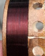
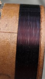
Here are couple of pictures of the 100 ohm voice coil for the JHP-51, as well as one of the JHP-52's 8ohm coil. Clearly the 100 ohm coil has much thinner wire. The length of the winding in both cases is about 8mm. One could count the turns for a layer to get the wire gauge, but I did not bother. Hard to tell, but I think it has two layers. The original coils are 2.0g. I don't know yet how much the Weber coils are.
Weber does have same size VC on nomex former, I'll get that one instead of the one on kapton former. The nomex is rated for less power (20W), but hey, the original rating on these speakers is only 15W. Thanks again for the recommendation.
The paper cone from Weber is 20g, which I think it is is pretty low for a 15" cone. Unfortunately I can't weigh the original cones. As I wrote above, one was ruined with spray paint; the other still has the spider and the spider clamp attached.
Here are couple of pictures of the 100 ohm voice coil for the JHP-51, as well as one of the JHP-52's 8ohm coil. Clearly the 100 ohm coil has much thinner wire. The length of the winding in both cases is about 8mm. One could count the turns for a layer to get the wire gauge, but I did not bother. Hard to tell, but I think it has two layers. The original coils are 2.0g. I don't know yet how much the Weber coils are.
Attachments
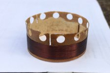
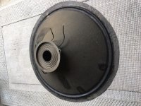
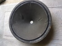
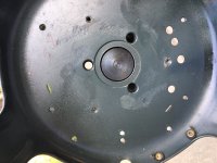
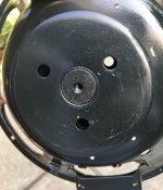
There is another interesting aspect of these speakers. The two pictures below show the magnet assembly from both sides. As you can see, there are three through-holes that connect the "outside world" to the air space under the spider, i.e. where the magnet gap and the voice coil is. I assume this was designed so to allow some airflow, perhaps to help cone movement and/or help with to help cooling? Btw, the dust cap is also vented, covered with felt or something like that.
In any case what it also means that dust and debris could get in there. So the bell covers in this case are not just for esthetics, they are needed to keep things clean inside. I do have one original bell cover, and I am getting a non-original one for the other speaker.
In any case what it also means that dust and debris could get in there. So the bell covers in this case are not just for esthetics, they are needed to keep things clean inside. I do have one original bell cover, and I am getting a non-original one for the other speaker.
Attachments
Thanks.
Left coil has 85 visible turns, so 170 total.
Given the 8mm winding length . they occupy almost 0.95 mm space, including enamel , adhesive ans wasted space, so about 0.8 to 0.85 mm diameter *copper*.
VERY fine wire for a woofer voice coil, winder has to go slow and have firm hands.
#39AWG would be 0.0889 mm copper wire, call it 0.089 or nominal 0.09 mm
Resistance is 848 ohm per 1000 ft so 2.78 ohm per meter.
#40 AWG would be 0.079756 mm copper wire, call it 0.008 mm
Resistance is 1070 ohm per 1000 ft so 3.5 ohm per meter.
Wire length is .032 m x Pi x 170=17 m
So:
#39 AWG would have 47 ohm DCR
#40 AWG would have 59.5 ohm DCR , closer to what you measured.
Let´s try #41 AWG
Tables I found do not supply ohms per 1000ft at such small diameters but should match 88 ohm DCR
Notice VC is multiperforated also, that again helps cooling.
Guess your new speaker will turn out fine.
Beware old high quality Alnico speakers used impossibly narrow gaps for better efficiency, *confirm* the modern VC fits with some clearance both inside and outside.
Shim it inside first, typical is 0.1 or 0.125 mm mylar/polyester/x ray film , then check you can freely move a 20/25mm wide strip *around¨*, between VC amd topplate hole walls.
I fear hole was punched for very fine wire 100 ohm coil and is too narrow for modern thicker wire.
Checking before assembly does not hurt and saves tears.
Minimum free space is printer paper thin.
Left coil has 85 visible turns, so 170 total.
Given the 8mm winding length . they occupy almost 0.95 mm space, including enamel , adhesive ans wasted space, so about 0.8 to 0.85 mm diameter *copper*.
VERY fine wire for a woofer voice coil, winder has to go slow and have firm hands.
#39AWG would be 0.0889 mm copper wire, call it 0.089 or nominal 0.09 mm
Resistance is 848 ohm per 1000 ft so 2.78 ohm per meter.
#40 AWG would be 0.079756 mm copper wire, call it 0.008 mm
Resistance is 1070 ohm per 1000 ft so 3.5 ohm per meter.
Wire length is .032 m x Pi x 170=17 m
So:
#39 AWG would have 47 ohm DCR
#40 AWG would have 59.5 ohm DCR , closer to what you measured.
Let´s try #41 AWG
Tables I found do not supply ohms per 1000ft at such small diameters but should match 88 ohm DCR
Probably.there are three through-holes that connect the "outside world" to the air space under the spider, i.e. where the magnet gap and the voice coil is. I assume this was designed so to allow some airflow, perhaps to help cone movement and/or help with to help cooling?
Notice VC is multiperforated also, that again helps cooling.
Guess your new speaker will turn out fine.
Beware old high quality Alnico speakers used impossibly narrow gaps for better efficiency, *confirm* the modern VC fits with some clearance both inside and outside.
Shim it inside first, typical is 0.1 or 0.125 mm mylar/polyester/x ray film , then check you can freely move a 20/25mm wide strip *around¨*, between VC amd topplate hole walls.
I fear hole was punched for very fine wire 100 ohm coil and is too narrow for modern thicker wire.
Checking before assembly does not hurt and saves tears.
Minimum free space is printer paper thin.
- Home
- Loudspeakers
- Full Range
- Jensen JHP-51, 100 ohm VC?