Hi folks
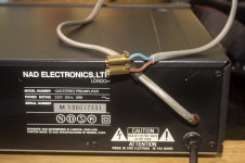
I picked up this preamp for a pittance because it was in horrible condition - absolutely filthy outside, covered in a sticky brown so thick that the light grey buttons had turned brown. It took quite a while to get it clean.
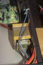
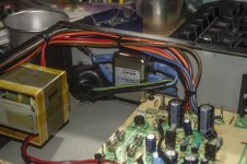
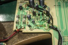
More worryingly, someone had added a twin core wire by drilling a hole in the back and it was clearly connected to the mains voltage, so I opened the amp and discovered the extra wires were connected to the on-off switch. I removed the extra wire and discovered the switch is bent at a funny angle, so it might need to be fixed.
While I had it apart, I decided to remove the fixed mains wire and replace it with a 3-pin IEC socket and a Schaffner noise filter. I also replaced the two large caps in the power supply section, they were only 470uF, I replaced them with 1000uF.
I picked up this preamp for a pittance because it was in horrible condition - absolutely filthy outside, covered in a sticky brown so thick that the light grey buttons had turned brown. It took quite a while to get it clean.
More worryingly, someone had added a twin core wire by drilling a hole in the back and it was clearly connected to the mains voltage, so I opened the amp and discovered the extra wires were connected to the on-off switch. I removed the extra wire and discovered the switch is bent at a funny angle, so it might need to be fixed.
While I had it apart, I decided to remove the fixed mains wire and replace it with a 3-pin IEC socket and a Schaffner noise filter. I also replaced the two large caps in the power supply section, they were only 470uF, I replaced them with 1000uF.
Attachments

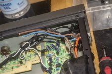
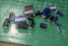
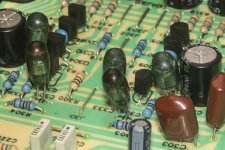
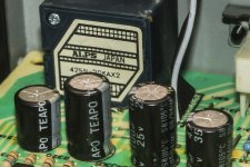
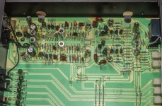
All the electrolytics in this thing are Teapo, not exactly high quality, so I decided I would replace the ones in the phono & preamp circuits - I won't be using the headphone socket so the ones on the headphone amp PCB can remain.
I happened to have all the right values in solid tantalum, so I used those as they are sounding rather nice in an integrated amp I recapped a while back, plus a couple of Phillips aluminum electrolytics - the small orange things. There were two 1000uF 10v electrolytics that I didn't have direct replacements for, so I used a couple of 1500uF 10v Rubycon MBZ which are low ESR and are supposed to be very good quality.
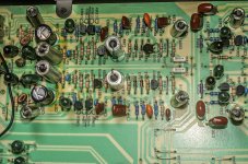
There are lots of these strange translucent green caps, never seen this type before, there are a few in the phono and preamp circuits plus one per channel on the inputs. I supposed these will be some sort of poly cap, but I'm thinking that, given the use of cheapo Teapo electrolytics, these green things are probably not very high end either and I'm wondering if I should replace them with polystyrenes as I have lots of those in my stash.
Anyone got any experience of these green translucent caps?
I happened to have all the right values in solid tantalum, so I used those as they are sounding rather nice in an integrated amp I recapped a while back, plus a couple of Phillips aluminum electrolytics - the small orange things. There were two 1000uF 10v electrolytics that I didn't have direct replacements for, so I used a couple of 1500uF 10v Rubycon MBZ which are low ESR and are supposed to be very good quality.
There are lots of these strange translucent green caps, never seen this type before, there are a few in the phono and preamp circuits plus one per channel on the inputs. I supposed these will be some sort of poly cap, but I'm thinking that, given the use of cheapo Teapo electrolytics, these green things are probably not very high end either and I'm wondering if I should replace them with polystyrenes as I have lots of those in my stash.
Anyone got any experience of these green translucent caps?
Attachments

Hi Mark
Hopefully they are polystyrene. I'll leave them be for the time being at least, applying the old 'if it ain't broke' principle...
Hopefully they are polystyrene. I'll leave them be for the time being at least, applying the old 'if it ain't broke' principle...
The SM on hifiengine suggests they're Polystyrene as well - most / all of the cap types are shown in the parts list.
Aah. cheers. that's good to know. I never thought to look for the SM to see if it listed the cap types.
And what is the verdict, does it sound different from before the recap ? Are you happy with the results ?
1I don't know, haven't tried it yet. I didn't listen to it before recapping so I don't know if it sounds different.
Tested it today, it works fine and sounds good, but I am having an issue where only one channel of my system is producing music. This is not anything to do with this NAD preamp, I haven't traced the fault yet, it's either the power amp or the active crossover.
Well, the preamp is definitely faulty, it was working great but today, after listening to music for about half an hour it suddenly just cut out and now isn't working. The fault lies in the preamp circuit as the headphone output works perfectly.
At normal listening level, nothing can be heard, but if you crank up the volume to about the 1 o'clock position you suddenly get music however it is badly distorted.
So I need to diagnose and fix the problem. Could it be one or more of the caps I replaced has failed? Or is it more likely to be the transistors? I have no idea but the circuit isn't that complex so hopefully, I can trace the fault and fix it.
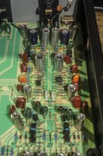
I took the lid off today and there are no visible signs of anything having failed, but then again, if a solid tantalum cap fails, what does it look like? There's no electrolyte to spew out...
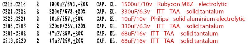
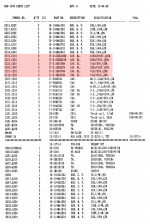
The only changes I made that are relevant were to replace the electrolytic caps, mostly with solid tantalums. I made a list of what caps I replaced and what the replacements were.
I have no idea how to go about diagnosing the problem and don't want to start replacing parts willy nilly, anyone got any tips as to where to begin?
Attachments

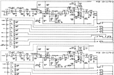

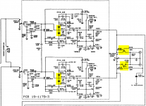
I'm thinking that the likely cause of the failure of a cap (if that is what has happened) would be overvoltage. On the schematic, I've marked the caps I replaced, and I noted that the two voltages marked are +24.5V and -22.5V.
I assumed that I was safe using caps that had voltage ratings as low as 6.3V because four of the caps that I removed were rated for 6.3V, but now I'm thinking that the position in the circuit of the 6.3v caps I used means they are subjected to more than 6.3v?
I assumed that I was safe using caps that had voltage ratings as low as 6.3V because four of the caps that I removed were rated for 6.3V, but now I'm thinking that the position in the circuit of the 6.3v caps I used means they are subjected to more than 6.3v?
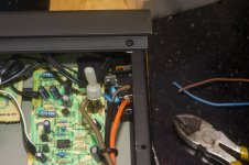
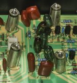
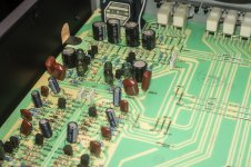
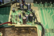
I might have located the problem. I noticed some clear-yellow liquid on the power section PCB, it's leaked out of one of the elctrolytic caps, I think it's come from C602, but C512 and C511 are right next to it and may also be the source.
So I removed all three of those caps and cleaned up the liquid. C602 was a 100uF 50v cap, but the manual gave a value of 47uf/63v. C512 and C511 were 220uF/35v and that is also what the manual states.
I didn't have the right values, but in order to just see if these caps were indeed the issue I replaced them with what I had handy - C602 with a 470uF/50v and C512 and C511 with 1000uF/35v. I had already replaced C501 and C502 with 1000uF/35v as those are the main filter caps in the PSU.
Attachments
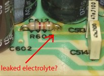

It was indeed the leaking cap(s) in the PSU. Replaced them and fired it up and it is once again making music.
Very lucky I spotted that tiny bit of clear-yellow liquid on the PCB.
Very lucky I spotted that tiny bit of clear-yellow liquid on the PCB.
The pics show similar marks of spillage elsewhere on that PCB. Perhaps those are signs of a finger being wiped to remove the gunk or some such activity by a previous tinker. They could also be flux, glue etc or just more awful quality electrolytic spillages. If you can decipher them, check the capacitor date codes for some clues.
Whilst tantalum caps are easy to fit, they are not the best or even reliable types of cap. Their use-by-date is often quoted as only 10 years and that passes quickly in regular use. Where possible for smaller values, use MLCC capacitor types. Even cheap, SMD versions in smaller values can be used to bridge the pads on the PCB underside if you wish. Otherwise, for polarized electrolytics, Panasonic FC and similar grade electrolytics do a really good job with audio - otherwise use Nichicon muse types for signal coupling where non-polarized type electrolytics are sometimes required.
Whilst tantalum caps are easy to fit, they are not the best or even reliable types of cap. Their use-by-date is often quoted as only 10 years and that passes quickly in regular use. Where possible for smaller values, use MLCC capacitor types. Even cheap, SMD versions in smaller values can be used to bridge the pads on the PCB underside if you wish. Otherwise, for polarized electrolytics, Panasonic FC and similar grade electrolytics do a really good job with audio - otherwise use Nichicon muse types for signal coupling where non-polarized type electrolytics are sometimes required.
You can improve this preamp quite significantly by adding an additional diode in the bias string to increase the quiescent current.
The additional diode reduces THD by a large margin.
Also, bypass those horrid series FETs with a relay. I used a relay with a 555 timer IC to give a few seconds delay at power on, to avoid thumps through the speakers.
.
The additional diode reduces THD by a large margin.
Also, bypass those horrid series FETs with a relay. I used a relay with a 555 timer IC to give a few seconds delay at power on, to avoid thumps through the speakers.
.
Attachments
Hallo Tony,
"Also, bypass those horrid series FETs with a relay. I used a relay with a 555 timer IC to give a few seconds delay at power on, to avoid thumps through the speakers."
What problems did you have with the fets, they work or do not work. Elaborate plse.🙂
"Also, bypass those horrid series FETs with a relay. I used a relay with a 555 timer IC to give a few seconds delay at power on, to avoid thumps through the speakers."
What problems did you have with the fets, they work or do not work. Elaborate plse.🙂
- Home
- Amplifiers
- Solid State
- NAD 1000 Preamp