-V Grid bias supplies can and have been done with diodes oriented either way. ie. with positive rail tied to the signal circuit ground as in a stacked supply, or negative rail out with ground to ground. Voltagewise they both add to the same but I wonder if there are undesirable effects from the positive supply rail connected to the signal circuit's ground when operating. Not good enough at LTspice to check it out that way myself - Can anyone offer comment?
Thanks
Thanks
Here's a sketch of the two. (I was waiting for edit permissions to put it on the original post. I thought the OP could edit the first post indefinitely.)
The story is, I already have a positive supply (like the one on the left) made up that I'd like to use for output tube grid bias as long as it's safe and just as good as a negative supply.
While the audio circuit is mostly tube and resilient, there are a couple of chips in it that might not be very forgiving . The amp is a new circuit I haven't tried yet so I want to be confident the positive supply can be considered equivalent to the negative one.
As far as I can tell, volts is volts, but . . . .
Attachments
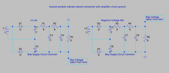
Don't go by labels like "rail" or "B+"; electrons can't read.
The only difference is which side the resistors are on. You could put them in either rail, alternating rails, or both rails. Assuming that your "L1" does not have some huge stray capacitance, the left side totally floats.
The only difference is which side the resistors are on. You could put them in either rail, alternating rails, or both rails. Assuming that your "L1" does not have some huge stray capacitance, the left side totally floats.
Last edited:
Don't go by labels like "rail" or "B+"; electrons can't read.
I wrote that so everybody would understand what I was asking, not to educate the electrons. They wouldn't listen to me anyway.
the left side totally floats.
Thanks for the confirmation. I wondered if there were issues not immediately apparent. Stuff like what difference there might be in response to grid current etc. A little knowledge can be nutriment for a lot of time wasting "What if"s.
The only practical difference is that in the left example the DC voltage potential of the transformer more closely tracks the negative voltage rail, whereas in the right example it more closely tracks ground. This is due to a 'ripple' voltage being dropped across the resistors. You get the choice of whether the ripple occurs between the transformer side and ground, or between the transformer side and the output rail. edit:actually that may not be strictly true, the AC magnitude is the same in both cases if the output has no ripple.
In high voltage supplies this may be also consideration for peak voltage presented across insulation. Also, the DC potential of the transformer is important if you're trying to generate multiple supply rails while sharing transformer secondary windings between each.
When using rectifier tubes, the choice between the two configurations is often made for you, since the heater supply is tied to the cathode for directly heated tubes, or there may be a maximum voltage limit between heater and cathode for indirectly heated tubes.
Last edited:
OK so either way is fine. But the electronics themselves are interesting and worth understanding. Not having a background in math beyond arithmetic I've never been able to get much of interest out of the texts I've looked at. This is an opportunity to learn some of that finer stuff, so I have to ask.
I've built quite a few circuits but have never considered a DC potential of the transformer. Is what you're referring to the drop from the rectified DC circuit return through copper resistance?
Also in your description above, I understand the words but don't know how to visualize what is meant by tracking as in "in the left example the DC voltage potential of the transformer more closely tracks the negative voltage rail, whereas in the right example it more closely tracks ground." Do you mean that in both cases it is tracking the bias supply common? What does "track" mean? Can you say a bit more?
Sorry for all the questions, but it's interesting beyond the confines of getting an amp built.
Thanks
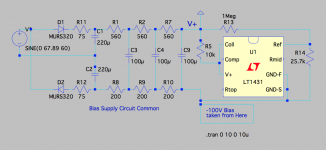
I am looking for a simple way to make use of the already built board with doubler and pi filters as is, with only the addition of the 431 circuit. (TO-92 LX1431 so no compensation circuit is needed.)
The 200Ω Rs in the common make the LT sim behave a little more smoothly on startup.
The 75Ω after the rectifier diodes are there to tame the startup ripple on the doubler caps which aren't rated for very much. (and I already have some 75Ω resistors.)
The 560Ω filter resistors can easily be changed so they're not all doing exactly the same thing but LT results make it look like it doesn't matter much.
I haven't seen a 431 used exactly this way before - usually shown on data sheets with the resistor above it to bias a parallel transistor that takes the voltage and current.
Is there any reason not to do it this way?
Attachments
- Home
- Amplifiers
- Power Supplies
- -V Grid Bias Supply - Positive or Negative?