Wonder what became of this one? Would be really fun one to try point to point. Assuming it would require careful matching of the output parts.
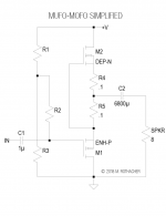
I don't know about matching required. According to Mike write-up, it's not a DEF amp. It is a MuFo, a Mu Follower. My interpretation of the circuit is that the upper depletion mode Mosfet is a CCS. I think it's a matter of selecting a Mosfet with Idss close to the chosen Iq and then adjust the source resistors R4 and R5 for fine tuning of Iq. Vds of the follower device is adjusted by adjusting the voltage divider which provides Vg to the gate. A trimmer resistor in the voltage divider would make the adjustment easy.
Conceptually, my latest project, the Mu Follower THF-51S, is similar. Because the THF-51S is a N channel device, the power supply polarity is reversed. And my CCS has more parts (similar to CCS in the BAF2015/Singing Bush except P channel Mosfet).
Conceptually, my latest project, the Mu Follower THF-51S, is similar. Because the THF-51S is a N channel device, the power supply polarity is reversed. And my CCS has more parts (similar to CCS in the BAF2015/Singing Bush except P channel Mosfet).
My thought was R4+R5 provides Vgs but the value of R4+R5 is small (0.2 Ohm) so with current of 1A for example, Vgs = -0.2V. So then the depletion mode M2 needs to be chosen to work with that Vgs, and possibly R4 and R5 could be adjusted to fine tune the current if necessary.
Or I could be totally misinterpreting your comment, and wandering off in the wrong direction.
I'm always eager to learn. 🙂
Going to LTSpice it!
Or I could be totally misinterpreting your comment, and wandering off in the wrong direction.
I'm always eager to learn. 🙂
Going to LTSpice it!
Attachments
Last edited:
It's kinda neat. It's a follower, no voltage gain. It can deliver 2A peak with Iq at 1.6A. If you make R4 and R5 .47 ohms, you can use an IXTH6N50D for the depletion part, and an IRFP920 for the enhancement part. The voltage divider formed by R1 and R3 are there to center the output. Use a 36V switcher for power. That should give you a 15 watt amp.
Eventually I will write-up the fleshed out thing and make PCBs or a kit, but this got pushed aside like many things. 🙂
Eventually I will write-up the fleshed out thing and make PCBs or a kit, but this got pushed aside like many things. 🙂
With R4 and R5 at 0.47 Ohm, that makes it easier to choose a N channel depletion mode Mosfet.
Finding Spice models is tough so I simulated the circuit with Sony VFETs up and down, and R4 and R5 were in the neigbourhood of 3 Ohms for Iq of 1.2A and supply of 60V. So Vgs around -7V or so. Seems to be in the ballpark for Sony VFETs.
Finding Spice models is tough so I simulated the circuit with Sony VFETs up and down, and R4 and R5 were in the neigbourhood of 3 Ohms for Iq of 1.2A and supply of 60V. So Vgs around -7V or so. Seems to be in the ballpark for Sony VFETs.
Last edited:
I’m thinking that one of the new VFET amp front ends would work well with this as the output stage. I’m becoming partial to the Bulwark, and can also recommend the Dreadnought.
- Home
- Amplifiers
- Pass Labs
- MuFo-MoFo