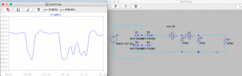
I find I have very poor luck with LTspice , no matter what I try to reduce the wandering lack of regulation - going to more filter sections , mixing RC with LC , changing values , I can't seem to eliminate the wandering irregular ripple.
OR . . . Is it that PSUD is lying to me and it's not going to be as easy to do things the way I like.
But for the diodes (no 1N4007 in LTspice - Highest Voltage Rated diode is 800) both sims are using identical values . Any instructive critiques? Most welcome if you have them !
Thanks !
OR . . . Is it that PSUD is lying to me and it's not going to be as easy to do things the way I like.
But for the diodes (no 1N4007 in LTspice - Highest Voltage Rated diode is 800) both sims are using identical values . Any instructive critiques? Most welcome if you have them !
Thanks !
Attachments
I would try adding ESR to the inductors and capacitors to tame the Q. If that doesn't help, I'm guessing the issue is that the sine source is floating when none of the diodes are conducting.
Tom
Tom
guessing the issue is that the sine source is floating when none of the diodes are conducting.
I did have series R set on the chokes but the capacitors didn't . Adding 1Ω series helped level the wandering but ripple amplitude still at 40+mA.
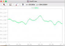
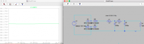
Is there any way to remedy the floating sine source? (I'm very unskilled at this!) [I did , just to throw a rock in the water to see what swims, put a ground on the - out of the sine source and attached is what it came up with. )
Thanks
Attachments
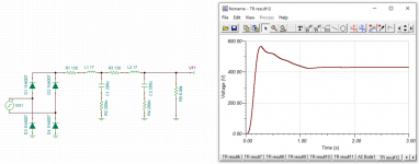
The problem is with the time steps selected by LTSPICE when you let it decide by itself and the max time is in the seconds.
Give LTSPICE a max timestep in the .tran command, one that is smaller than the line frequency, say 10us.
.tran 0 30 0 10u works as expected when I tried it ...
Give LTSPICE a max timestep in the .tran command, one that is smaller than the line frequency, say 10us.
.tran 0 30 0 10u works as expected when I tried it ...
Last edited:
That's pretty odd. The time step looks to be pretty short already.
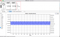
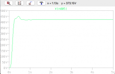
I tried in TINA-TI (sorry, I can't stand LT Spice's UI). Here's what I get. I set the max step to 100 us.
The overshoot on startup is a bit concerning. Yes. This is with sine wave input.
TINA-TI doesn't show much ripple. But then neither does PSUD. Look at the Y axis divisions.
Tom
I tried in TINA-TI (sorry, I can't stand LT Spice's UI). Here's what I get. I set the max step to 100 us.
The overshoot on startup is a bit concerning. Yes. This is with sine wave input.
TINA-TI doesn't show much ripple. But then neither does PSUD. Look at the Y axis divisions.
Tom
Attachments
You can use the more accurate 'alternate solver' under the configuration. Also you can adjust the precision used.
I always add ESR for caps, inductors and voltage sources. As the system gets larger you'll find the solver finds it more difficult to get a stable point.
LTSpice you can add things to it (some manufacturers have models todo this).
If that first choke isn't a full swing then perhaps adding a little 47uF cap between the diode and choke may help.
Another hint:
if your simulation runs from - say 0 to 30 seconds
and you display just the steady state signal from 29 to 30 seconds
you don't see much but a thin line ...
now, just click on the display node again a second time to view it magnified and in full detail
if your simulation runs from - say 0 to 30 seconds
and you display just the steady state signal from 29 to 30 seconds
you don't see much but a thin line ...
now, just click on the display node again a second time to view it magnified and in full detail
I can't seem to make it work that way on Mac OS. I have to drag the magnifier across the trace a few times to open it up. Either that or reset the scale on the Y axis.
If you're only interested in the last second or fraction of a second, you can add a parameter to the .TRAN command such that it only saves the bit you're interested in. Then the plot will autoscale to that length. That can sometimes speed up the simulation as well.
I forget the syntax but if you google/bing/alta-vista "SPICE .TRAN syntax" you'll likely find it.
Tom
I forget the syntax but if you google/bing/alta-vista "SPICE .TRAN syntax" you'll likely find it.
Tom
PSUD2 uses an effective resistance in the PT supply - is that also used in the LTSpice model ? You can also include a high resistance from PT winding to ground, to provide a non-infinite floating circuit (as Tom indicated) in LTSpice.
Such high resistance is usually included in the form of a minimum conductance, GMIN. It's typically something like 1e-12.
Tom
Tom
If the wandering ripple is related to numerical convergence at diode commutation then lowering GMIN in the diode model, or parhaps the easier addition of a resistor, is worth a check (eg. 10 Meg).
It may also be worthwhile adding a small cap on the bridge to choke node, to also ease numerical convergence for a choke input filter.
It may also be worthwhile adding a small cap on the bridge to choke node, to also ease numerical convergence for a choke input filter.
Last edited:
OP seems to have it resolved with a lower minimum step size, which doesn't really make sense to me. But whatever. I'm a bit more in tune with the Care and Feeding of Spectre than of SPICE. 🙂
Tom
Tom
Yes, with Sorento's prescribed time step change the wandering voltage ripple is gone and results are more as I'd thought/hoped they should be - not that my expectations are built on understanding anywhere remotely close to the level of yours.
"Numerical Convergence at diode commutation"? I get some sort of vague image of numbers approaching zero from both sides. Maybe I'd better wait to ask about that another time. : )
Thanks again.
"Numerical Convergence at diode commutation"? I get some sort of vague image of numbers approaching zero from both sides. Maybe I'd better wait to ask about that another time. : )
Thanks again.
- Home
- Amplifiers
- Power Supplies
- LTspice and PSUD , never the twain . . . . . .