Hello!
I have a speaker restoration project with missing parts on the crossover, i got the component values and types from a helpful member on another forum.
I made some drawings from the crossover (not a professional). Can somebody explain how this crossover is working (mainly the woofer section) and what it does? I have the very basic knowledge of crossovers but i haven't seen this type of crossover when trying to find from different forums.
Second question is about capacitors. I know that the tweeter capacitor is MKT 160V 3,3uF and woofer capacitors 68uF and 22uF are raw electrolytics 100V. Can i use modern MKP capacitors on the smaller 22uF and 3,3uF values or should i stay with electrolytics?
I will be very happy if somebody have time and knowledge to answer these questions. 🙂
Attachments
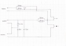
The two woofers are in series connection. Are you sure there is a connection between the junction of the two woofer and the junction of of the 12Ω and 68µF capacitor? I suspect this is incorrect and there is no connection.
The inductor is the first low pass component, and 22µF is there to bypass to ground high frequencies that get through the inductor, making it appear like second order crossover (12dB per octave). However the resistor in parallel with the inductor will limit the maximum attenuation at higher frequencies that the inductor creates, turning that section in to a shelving filter, and the ultimate crossover slope first order (6dB per octave).
The 12Ω and 68µF capacitor are a 'Zobel' network to correct the rising impedance from the self-inductance of the woofers' voice coils. This makes the woofers approximate a resistive load; without it, the crossover would not achieve the ultimate slope it is supposed to.
The 3.3µF capacitor is a high pass filter and being the only reactive component makes the tweeter crossover first order. The 1.8Ω in series with the tweeter and the 10Ω shunt to ground form an attenuator to reduce the tweeter output to balance with the woofers. The self-inducatance ot the tweeters voice coil does not affect the slope of the crossover, so there is no need for a Zobel correction circuit for the tweeter.
Many people will scoff at this statement but because both the capacitors in the bass section of the crossover are passing audio, audio grade capacitors should be used. Whether there is going to be a worthwhile improvement from changing the 22 and 68µF capacitors to film capacitors really depends on how good everything else in the system is. With a particularly well sorted 'high end'-ish speaker system I have I was shocked to hear quite a bit of improvement when a replaced all electrolytics with audio grade crossover film capacitors.
Thank you for your fast response!
I need to read your post few times more that i understand everything that you write. 🙂
I checked the crossover again and verified that there really is a connection from between 12Ω resistor and 68uF capacitor to the junction of two woofer.
Yeah, i have read all this debate about changing electrolytics to film capacitors and how that can change the overall speaker balance with different ESR and other factors.
The crossover board is quite small so the 68uF film capacitor wont fit to it. I quess i try the 3,3uF and 22uF with film caps and 68uF with electrolytic.