Better Audio by UHF/RF jFET's/MOSFET's Replacement for 2SK389/2SJ109 and 2SK170/2SJ74 (<5pF) ?
Is the use from the extremely popular Toshiba's complementary Dual jFET's 2SK389/2SJ109 and single jFET's 2SK170/2SJ74 really a good choice (e. g. for a so called true complementary input differential amplifier stage) ?
For the most developers in audio clearly yes - so I think.
Example is in post #45 under
Pass X250 repair
and
JFET/MOSFET complementary-differential preamplifier
and the attachments.
Particularly the dual jFET's 2SK389/2SJ109 are mainly to find in very expensive power amplifiers.
In the meantime I have strong doubts whether the 2SK389/2SJ109 used both for a single and differential input stages (LTP) were and are really the first choice. I think, there are disadvantages as follow:
1) All are hard to find as NOS from Toshiba
2sk389 and 2sj109 -where
The next best thing to 2SK389 / 2SJ109 ?
2sk389 2sj109 NO FAKE!!!!
Replacement For Toshiba 2SK170/2SJ74
2) Not really low and additional different input capacitance between N-and P channel version
(N-channel approximately 20pF, but P-channel version nearly 100pF (!!), i. e. 5 times more - this means for me no true complementary character).
https://pdf1.alldatasheet.com/datasheet-pdf/view/30769/TOSHIBA/2SK389.html
https://pdf1.alldatasheet.com/datasheet-pdf/view/30517/TOSHIBA/2SJ109.html
https://pdf1.alldatasheet.com/datasheet-pdf/view/30559/TOSHIBA/2SJ74.html
https://pdf1.alldatasheet.com/datasheet-pdf/view/30581/TOSHIBA/2SK170.html
Input capacity of integrated operational amplifiers with good sonic character and jFET inputs are much more low - in case of AD817: only 1,5pF.
Thus jFET's and MOSFETs as follow are the best choice for input stages:
2N5484-5486, BF244, BF245 3-8mS 3-5pF
https://pdf1.alldatasheet.com/datasheet-pdf/view/173154/FAIRCHILD/BF244B.html
BF256 3mS, 1pF
https://pdf1.alldatasheetde.com/datasheet-pdf/view/172151/ONSEMI/BF256A.html
https://pdf1.alldatasheet.com/datasheet-pdf/view/77367/MOTOROLA/BF256C.html
BFR1105 30mS, 2,2pF Vds only 7V max
https://www.nxp.com/docs/en/data-sheet/BF1105_R_WR.pdf
BF961 12-15mS, 1,6pF
https://pdf1.alldatasheetde.com/datasheet-pdf/view/95965/VISHAY/BF961.html
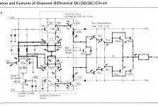
Due the low voltage and the low Gm the approach from Fig. 4.2D in the fourth image and under
http://peufeu.free.fr/audio/memory/memory-4-circuits.html
will be a perfect solution - so I think.
Q1 and Q2 is to replace by the low voltage/low gm FET's mentioned before (R11/12 determines the current flow through the input FET's) and the jFETs J3+J4 in fig. 4.2 D by a high voltage video BjT or two medium voltage BjT like BD139/BD140 in case of high voltage supply (medium power outline TO126) for a cascode configuration - similar to the second stage in fig. 5.7 under
http://peufeu.free.fr/audio/memory/memory-5-vas.html
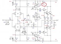
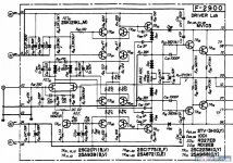
The co called true complementary LTP input stage like schematic from first image should be to avoid (second and third image shows a solution without p-channel jFET's).
What could be wrong with this consideration?
Is the use from the extremely popular Toshiba's complementary Dual jFET's 2SK389/2SJ109 and single jFET's 2SK170/2SJ74 really a good choice (e. g. for a so called true complementary input differential amplifier stage) ?
For the most developers in audio clearly yes - so I think.
Example is in post #45 under
Pass X250 repair
and
JFET/MOSFET complementary-differential preamplifier
and the attachments.
Particularly the dual jFET's 2SK389/2SJ109 are mainly to find in very expensive power amplifiers.
In the meantime I have strong doubts whether the 2SK389/2SJ109 used both for a single and differential input stages (LTP) were and are really the first choice. I think, there are disadvantages as follow:
1) All are hard to find as NOS from Toshiba
2sk389 and 2sj109 -where
The next best thing to 2SK389 / 2SJ109 ?
2sk389 2sj109 NO FAKE!!!!
Replacement For Toshiba 2SK170/2SJ74
2) Not really low and additional different input capacitance between N-and P channel version
(N-channel approximately 20pF, but P-channel version nearly 100pF (!!), i. e. 5 times more - this means for me no true complementary character).
https://pdf1.alldatasheet.com/datasheet-pdf/view/30769/TOSHIBA/2SK389.html
https://pdf1.alldatasheet.com/datasheet-pdf/view/30517/TOSHIBA/2SJ109.html
https://pdf1.alldatasheet.com/datasheet-pdf/view/30559/TOSHIBA/2SJ74.html
https://pdf1.alldatasheet.com/datasheet-pdf/view/30581/TOSHIBA/2SK170.html
Input capacity of integrated operational amplifiers with good sonic character and jFET inputs are much more low - in case of AD817: only 1,5pF.
Thus jFET's and MOSFETs as follow are the best choice for input stages:
2N5484-5486, BF244, BF245 3-8mS 3-5pF
https://pdf1.alldatasheet.com/datasheet-pdf/view/173154/FAIRCHILD/BF244B.html
BF256 3mS, 1pF
https://pdf1.alldatasheetde.com/datasheet-pdf/view/172151/ONSEMI/BF256A.html
https://pdf1.alldatasheet.com/datasheet-pdf/view/77367/MOTOROLA/BF256C.html
BFR1105 30mS, 2,2pF Vds only 7V max
https://www.nxp.com/docs/en/data-sheet/BF1105_R_WR.pdf
BF961 12-15mS, 1,6pF
https://pdf1.alldatasheetde.com/datasheet-pdf/view/95965/VISHAY/BF961.html
Due the low voltage and the low Gm the approach from Fig. 4.2D in the fourth image and under
http://peufeu.free.fr/audio/memory/memory-4-circuits.html
will be a perfect solution - so I think.
Q1 and Q2 is to replace by the low voltage/low gm FET's mentioned before (R11/12 determines the current flow through the input FET's) and the jFETs J3+J4 in fig. 4.2 D by a high voltage video BjT or two medium voltage BjT like BD139/BD140 in case of high voltage supply (medium power outline TO126) for a cascode configuration - similar to the second stage in fig. 5.7 under
http://peufeu.free.fr/audio/memory/memory-5-vas.html
The co called true complementary LTP input stage like schematic from first image should be to avoid (second and third image shows a solution without p-channel jFET's).
What could be wrong with this consideration?
Attachments
-
 2SJ109-2SK389 input.jpg93.2 KB · Views: 2,537
 -
 diamond differential circuit.JPG109.6 KB · Views: 1,723
 -
 Sansui G-2200.jpg101.1 KB · Views: 1,482
 -
 input-evolution.gif8.1 KB · Views: 1,467
 -
Ultra High Zin Buffer - National Semiconductor FET Databook 1977.pdf43.4 KB · Views: 350
-
sziklai National Semiconductor FET Databook 1977.pdf43.9 KB · Views: 281
-
Sziklai-Darlington-II-Theory and applications of field-effect transistors.pdf184.3 KB · Views: 218
-
Theory and applications of field-effect transistors.pdf1.3 MB · Views: 627
Last edited:


42 (number - Wikipedia)
... I don't understand anything to the context in post 1
I better upload the questions there ??
Audiokarma Home Audio Stereo Discussion Forums
Last edited:
what is the purpose of zillion links and pages to read? somebody is in the prison and has 30years of free time?😀
opinion need to be short and direct, in one row
opinion need to be short and direct, in one row
You are right in the case of solutions to simple issues.what is the purpose of zillion links and pages to read? somebody is in the prison and has 30years of free time?😀
opinion need to be short and direct, in one row
Is this here the case ?
post #25-30 under
https://www.diyaudio.com/forums/hea...ltra-low-noise-suggestions-3.html#post5606660
gives some interesting advice
Last edited:
in the quotation from post #11 under
Ultra low noise amp with JFET's - How to reduce the THD ??
was pointed out an important fact.
Ultra low noise amp with JFET's - How to reduce the THD ??
was pointed out an important fact.
Does anyone know if these are legit?
NOS 2SJ109-V J-FET DUAL N-CHANNEL VERY RARE LOW NOISE HIGH GAIN ORIGINAL | eBay
NOS 2SJ109-V J-FET DUAL N-CHANNEL VERY RARE LOW NOISE HIGH GAIN ORIGINAL | eBay
How about GaAs FET?
Some ultra-low noise GaAs FETs are being manufactured, but I don't know whether they still have very low noise levels at audio frequencies, and whether the linearity is suitable for audio amplifiers.
Some ultra-low noise GaAs FETs are being manufactured, but I don't know whether they still have very low noise levels at audio frequencies, and whether the linearity is suitable for audio amplifiers.
2) Not really low and additional different input capacitance between N-and P channel version
(N-channel approximately 20pF, but P-channel version nearly 100pF (!!), i. e. 5 times more - this means for me no true complementary character).
From my simulations, the capacitance is not as bad as it looks. Apparently there is some capacitance cancellation when you use the full complementary arrangement. I think capacitance was correctly modelled in the models I used.
Curve match is more important than capacitance match. When I finally use mine, I'll use the method by EUVL to get their curves matched. Search for "Input Jfet Variants" (PDF by EUVL).
- Home
- Amplifiers
- Pass Labs
- Better Audio by UHF/RF jFET Replacement (<5pF) for 2SK389/2SJ109+2SK170/2SJ74