I would like to build a balanced RIAA amplifier capable of an MC cartridge with 0.2 mV output. I have been looking at Allen Wright's RTP amplifiers and Morgan Jones' balanced hybrid RIAA amplifier described in his book "Valve Amplifiers" fourth edition on pages 628-645. I like MJ's design since it is quite well described and draws a lot less power than AW's designs. However, MJ's RIAA stage is designed to give 4 Vrms output with 0.3 mVrms in to match balanced digital sources. I don't use any digital sources and my line stage is designed for 250 mVrms input. Therefore, I would like to reduce the gain.
Ideally, I would like to show the schematic here, but I guess that it would violate the copyright. Hopefully, a few of you have a copy of MJ's book.
The first stage is a cascode with a transistor and an E88CC tube in each leg. MJ writes that the gain can be changed to adjust for imbalance between the channels from the cartridge by adjusting the current in the first stage and gives the following equations:
A = gm * Rl
gm = 35 * Ic
3 mA is passed in each leg of the first stage. If my math is right, I would need to reduce the gain in the first stage with a factor of 10, which would reduce the current to 0.3 mA. Would this be feasible?
I could also reduce the gain by reducing the anode resistors Rl.
Reducing the gain of the second stage is also a possibility.
Can this RIAA amplifier be successfully tweaked to suit my requirements? If so, what would the best way be?
Reducing the current might ( will?) impair linearity.
Why not build the stage as documented and adapt a resistive voltage divider at the output ?
Why not build the stage as documented and adapt a resistive voltage divider at the output ?
The usual rule is that, all else being equal, gm is proportional to the cube root of current, and gain (mu) is independent of current anyway.
to change the gain, it's more effective to use different tubes, or add resistive attenuators at suitable places, and choose the current for noise and bias voltage requirements.
to change the gain, it's more effective to use different tubes, or add resistive attenuators at suitable places, and choose the current for noise and bias voltage requirements.
Reducing the current might ( will?) impair linearity.
That is my concern, but I am not sure. Does anyone know what the effect of running E88CC on 0.3 mA?
Why not build the stage as documented and adapt a resistive voltage divider at the output ?
Amplifying the signal, then attenuate it and amplify it up again doesn't seem like the way to the best performance. I guess that it would increase noise and distortion compared to having only the required gain in each stage.
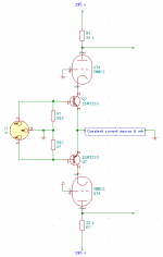
Without violating the copyright, I hope that I can show the initial stage (see below).
The stage consists of two cascodes with a tube and a transistor. From what I have read on cascodes with two tubes, if there is an unbypassed resistor, Rk, on cathode of the lower tube, the gain is reduced with a factor:
1/(1+gm*Rk)
I guess that this would also work when the lower element is a transistor. Adding 82 ohm resistors under the collectors would degenrate the transconductance and therefore the gain with a factor of 0.1, which would about the right total gain for me. The voltage drop over the resistors would be 0.25 V. This might not mess up the operating point of the transistors too much? 😕
Attachments
If you add a potentiometer between the emitters and the CCS you can:
- increase linearity of the stage;
- reduce gain as you want;
- balance the stage.
Are you sure grids of the triodes are grounded and not referenced to an higher voltage?
I've widely used that kind of stage as phase splitter in PP amp, an I ended preferring a tube on the bottom and a ss device on top.
That is my concern, but I am not sure. Does anyone know what the effect of running E88CC on 0.3 mA?
As is each triode runs at 3mA, reducing current lowers the load line and usually increases gain in a resistive loaded stage.
You could try subbing the ECC88's for ECC82's, 6CG7's etc for less gain. As your operating over such a very small length of the load line linearity shouldn't be effected. Knock it upon the bench and test. Make your CCS variable with a preset in the emitter R and use a 6v2 zener to fix the base.
Andy.
SSM2210 datasheet suggests 1mA across each transistor:
404 Not Found[50].pdf
So an ECC83 should fit better.
You can find the schematic I was talking about here:
improvements on 12AX7 12AT7 EL34 schematic?
That inspired this other amp:
100W + 100W amp to share
404 Not Found[50].pdf
So an ECC83 should fit better.
You can find the schematic I was talking about here:
improvements on 12AX7 12AT7 EL34 schematic?
That inspired this other amp:
100W + 100W amp to share
A = gm * Rl
gm = 35 * Ic
Can this RIAA amplifier be successfully tweaked to suit my requirements? If so, what would the best way be?
The linear way to reduce transconductance is to add series resistance to the emitters (also called degeneration). Each resistor adds to the reciprocal of transconductance. So:
Gm (total) = reciprocal of (the sum of added resistor plus reciprocal of transistor Gm).
All good fortune,
Chris
The linear way to reduce transconductance is to add series resistance to the emitters (also called degeneration). Each resistor adds to the reciprocal of transconductance.
Thanks Chris! This sounds like the way to go. 🙂
Is there any risk that the voltage drop of 0.25 V across the 82 ohm resistor will shift the operating point of the transistor too much? 😕
The constant current source will need to operate down 0.25 VDC lower with common-mode signal swing, but the signal transistors won't know anything about it. They live in a constant current paradise.
All good fortune,
Chris
All good fortune,
Chris
Thanks again Chris! Now, I know how to proceed. 🙂
The E88CC will be less linear at 0.3 mA See :That is my concern, but I am not sure. Does anyone know what the effect of running E88CC on 0.3 mA?
Amplifying the signal, then attenuate it and amplify it up again doesn't seem like the way to the best performance. I guess that it would increase noise and distortion compared to having only the required gain in each stage.
<snip>
😕
https://frank.pocnet.net/sheets/009/e/E88CC.pdf
Reducing signal with a resistive divider adds zero dist and keeps the properties of the riaa-amp. The only thing that differs is that you can open up the volume pot ( another resistive divider) in your amp.
The resistive divider adds noise. In itself, it may not add distortion, but higher amplification usually gives higher distortion. I think that keeping the original design and amplifying the signal to 4 Vrms, then attenuating it and finally amplifying it again is very likely to give more distortion than the approach that Chris suggested.
If you like Morgan Jones designs? Why not look at his 3-valve phono design. It is not designed for mc but since you only need 250mv output, it would fit nicely with a 1:4 transformer in front of it. It even comes with a reasonably priced pcb.
- Home
- Amplifiers
- Tubes / Valves
- Morgan Jones' Balanced Hybrid RIAA Stage