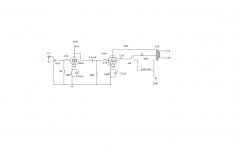
I just built this today and sounds as good as the 6l6 6h9c i built , again if I have done something wrong please comment and tell me if wrong. Bass is very strong mids to high are also very good.
Attachments

Nice build!
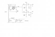
There is no anode resistor for the 6DJ8 in your schematic.
The cathode voltage of the 6DJ8 is 4 V according to your schematic. The current would than be about 22 mA (I = V/R = 4/180 = 0,022 A) which is abnormaly high. If the anode voltage would realy be 225 V than the dissipation would be: P = I x V = 0,022 x 221 = 4.9 Watt which would be way over the limit of the 6DJ8.
Nice build!
There is no anode resistor for the 6DJ8 in your schematic.
The cathode voltage of the 6DJ8 is 4 V according to your schematic. The current would than be about 22 mA (I = V/R = 4/180 = 0,022 A) which is abnormaly high. If the anode voltage would realy be 225 V than the dissipation would be: P = I x V = 0,022 x 221 = 4.9 Watt which would be way over the limit of the 6DJ8.
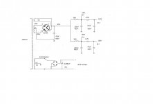
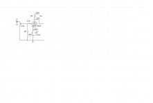
Ok new multi meter with new battery, re-checked all solder joints and put a anode resistor in now here is all new voltage reading. hope it all right now??
Attachments
You might want to aim for 2V or even 2.5V on the cathode of the 6DJ8.
The reason for that is that the 6DJ8 has a gain of about 25X, and the grid bias of the EL34 is 22V.
The 6DJ8 has to drive at least 22V into the EL34 grid.
With 1V on the 6DJ8 cathode, the most signal it can accept is about 1V.
1V x 25 gain = 25V, which is just barely enough to drive the EL34.
However, if you had 2.5V on the 6DJ8 cathode, it could accept almost the full output of a DAC or CD player (2V or so) and could drive the EL34 with 2V x 25 = 50V.
That means you'll have headroom, or extra voltage swing in reserve for if/when you need it.
A good operating point for the 6DJ8 might be
plate voltage = 100V,
cathode voltage = 2.5V
plate current = 7mA
To get 2.5V cathode voltage with 7mA plate current:
2.5/0.007 = 357 ohms so 360R is close enough.
To find out the plate load resistor:
330V - 100V = 230V
230V with 0.007A through it will require x value resistor?
230/0.007 = 32,587 ohms, so 33k will be close enough.
So,
B+ = 330V
Vp = 100V
Vk = 2.5V
Ip = 7mA
Rp = 33k
Rk = 360R
That 33k resistor will be dropping 230V, so 230*0.007 = 1.61W
It'll get hot. I'd use a 5W rated resistor, minimum.
Give it a try, see what happens. The voltages should end up within 10% of the predictions.
--
Attachments
Last edited:
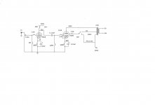
Thanks did the mods and still happy with sound seems a little better, look at preamp schematic attach Sorry just saw a mistake should be 380R not K
Attachments
Last edited:
- Home
- Amplifiers
- Tubes / Valves
- Simple EL34 6DJ8 Tube Amplifier