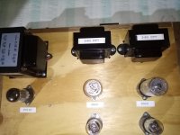
Looks nice, any pictures? I am assuming the 6N3C is loaded 'correctly' (I am not checking datasheets).
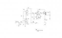
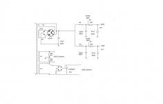
My only question: The 5y3 handles 47uF? How is the ripple noise? If tolerable I would reduce the first cap to 10uF. Your circuit is pulling ca 120mA at ca 300V, looks like close to max of the 5Y3 ratings. Any need for derating rectifiers or are they always conservative rated on datasheets so there is no need to derate?
My only question: The 5y3 handles 47uF? How is the ripple noise? If tolerable I would reduce the first cap to 10uF. Your circuit is pulling ca 120mA at ca 300V, looks like close to max of the 5Y3 ratings. Any need for derating rectifiers or are they always conservative rated on datasheets so there is no need to derate?
The bias of the 6H9C (-1 V) is a bit low for my taste but it sounds very nice so this is not a problem.
I assume you did not earth the winding for the filaments of the 6H9C's because of the maximum cathode to heater voltage of the 6H9C (I think it is 100 V). If you would want to earth it, you have to 'lift' the winding a bit (to about 50 Vdc).
It surprises me that you only reach 305 Vdc from a 310 Vac winding with a bridge configuration.
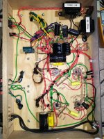
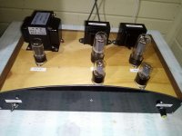
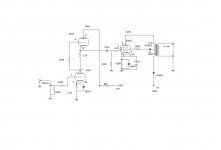
I just built this amp and sounds very nice, can anybody see any problems??
Ok I just did a few changes and did 6l6gc and changed rectifier to GZ34S and voltages changed but still got a great sound
Attachments
Huh? So the bias of the 6H9C went up from -1 V to -4 V while B+ only went up from 250 V to 266 V?
You don't drop the voltage by inserting non decoupled resistors in series with the tubes ... That SRPP is not working right with 68K in the anode of the top tube.
Those 10K resistors in the power supply should be increased until you have the right voltage .
Those 10K resistors in the power supply should be increased until you have the right voltage .
Last edited:
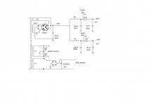
The output tube self bias resistor is 330 Ohms.
To bypass it, normally use a capacitor that has capacitive reactance 1/10 of that, or 33 Ohms across the audio frequency range.
The 1.5uF cap that is in parallel with the 220uF there should not be needed (unless the 220uF electrolytic is not a quality one).
1.5uF is 330 Ohms at 321 Hz, and is 33 Ohms at 3,210Hz.
Any decent 220uF electrolytic should be able to properly bypass a 330 Ohm resistor all the way from 20Hz to beyond 20kHz.
Listen to the amplifier with the 1.5uF cap, then listen it without the 1.5uF cap.
The diode in the output tube screen is not needed.
Listen to the amplifier with the screen diode, than listen to the amp with a short across the diode.
The diode from the B+ to the 3.5k output transformer primary should not be needed.
Listen to the amplifier with that diode (B+ to output transformer primary), than listen to the amp with a short across that diode.
And please report what you heard, on those 3 listening tests (That is a nice simple but fundamentally good circuit). Others may want to build that amplifier, and there are 3 parts that most likely that are not needed.
Thanks guys will do everything that was suggested and report back got to set it all back up on my work bench and I'm off today to buy a better multi meter I feel the one I'm using is not giving true readings.
The output tube self bias resistor is 330 Ohms.
To bypass it, normally use a capacitor that has capacitive reactance 1/10 of that, or 33 Ohms across the audio frequency range.
The 1.5uF cap that is in parallel with the 220uF there should not be needed (unless the 220uF electrolytic is not a quality one).
1.5uF is 330 Ohms at 321 Hz, and is 33 Ohms at 3,210Hz.
Any decent 220uF electrolytic should be able to properly bypass a 330 Ohm resistor all the way from 20Hz to beyond 20kHz.
Listen to the amplifier with the 1.5uF cap, then listen it without the 1.5uF cap.
The diode in the output tube screen is not needed.
Listen to the amplifier with the screen diode, than listen to the amp with a short across the diode.
The diode from the B+ to the 3.5k output transformer primary should not be needed.
Listen to the amplifier with that diode (B+ to output transformer primary), than listen to the amp with a short across that diode.
And please report what you heard, on those 3 listening tests (That is a nice simple but fundamentally good circuit). Others may want to build that amplifier, and there are 3 parts that most likely that are not needed.
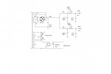
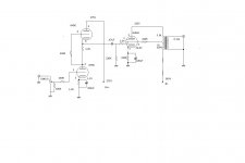
Wow yes what a difference taking those parts out made, bass increased that is all I could notice removing the parts. This is the updated schematics I think that's all the tweaking I need to do?.
Attachments

Just a curiosity:
You have B+ at 345V, the UL screen tap at 330V, and the Plate at 325V.
345V - 325V = 20V, B= to Plate
345V - 330V = 15V, B+ to Screen
With those voltage drops versus DCR, it appears that you may be operating the UL at
approximately 75%.
75% might be a good thing, it is a tradeoff of many characteristics, including maximum power, and distortion.
You may have found the sweet spot for your complete playback system.
If it sounds good, then enjoy listening to it.
But we do not know the % for sure, because we do not know the DCR from B+ to the UL tap, and DCR from the UL tap to the Plate.
And we do not know the lengths of the turns from B+ to UL tap, and UL tap to plate.
We also do not know the real turns ratios.
The only way to know the UL percent for sure, is to measure the Signal Volts on the Screen, and the Signal volts on the plate.
But some scope probes and inputs are not rated for 330V plus AC signal, and even if they are rated for that much, we still should only use a small signal to test those screen and plate voltage ratios.
UL at 75% has lower gain and lower output impedance (higher damping factor), than a 40% UL tap.
UL at 75% is closer to Triode Mode, than 40% UL.
Swapping the B+ and Plate leads on the primary will change the UL %, but will also change the phase by 180 Degrees.
Now we might be 25% UL.
But not certain, we still have to measure the AC voltages.
A good multimeter on AC should be able to measure that, if the signal is small, and the frequency is only 1 kHz.
Last edited:
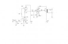
Its kind of a silly question perhaps, but shouldn't pin '8' be connected to pin '1' on the 6N3C?
The designation "6L6" is for the original, all-metal version in which pin 1 is connected to the metal envelope. In the later glass versions pin 1 is not connected.
- Home
- Amplifiers
- Tubes / Valves
- any problems seen?? 6n3c 6h9c tube amplifier