I am not going to profess to being an expert or anything when it comes to electronics or especially audio circuitry, so I was hoping to get some feedback and/or that some people more knowledgeable than I would "check my homework", so to speak.
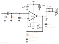
Here is the current draft of a schematic on which I am working, based on the examples in the datasheets for the LM1875, LM1876, and LM3886; Scott Campbell's "A Complete Guide to Design and Build a Hi-Fi LM3886 Amplifier"; and various information gleamed from this forum, particularly the advice of AndrewT.
I have tentatively selected the LM1875 (for its low distortion) — though it is otherwise a bit of an overkill, as I do not anticipate ever exceeding 2~4W.
Bipolar capacitors are film (my best guess as to what AndrewT meant by "MKP"), the polarized ones are audio-grade electrolytics, and the resistors are metal film (preferably with ≦0.5% tolerance — though that is my own preference).
I explain my high-band/low-band cutoffs in grey near their applicable parts in the schematic. Mouser was referenced for a rough idea of cost and availability of less common sizes. (9.98kΩ, for example.)
Source will be a computer's line-out, so I am guessing that a 10kΩ input impedance would be optimal, and a gain of 10 or 11 should more than suffice. (Also should help with reducing Johnson–Nyquist noise, compared to the values used in the datasheet, per my understanding.)
Question #1:
From a theoretical standpoint, does anyone see anything wrong with my numbers, or am I on the right track? Is anything absent that I should add?
Question #2:
In the case of a pure DC voltage source (batteries, for example), C3, C4, C6, and C7 are unnecessary, no? To the extent of my understanding, their purpose is to "fill the void" between peaks of one polarity of the AC voltage swing, no? Therefore, with a steady DC source, unnecessary, no? (There is also a discrepancy in the datasheet regarding the size of C6 and C7, with the typical application schematic saying 100μF and the recommended board layout showing 1000μF... And I also see people on here adding a third...)
Question #3:
I have seen suggestions of using large polarized capacitors in series with the speaker, as a means to protect it in the event of catastrophic failure of the LM1875. However, such nullifies the advantage of the split supply, no? (Perhaps a reason to opt for the LM1876, instead, I wonder?)
Question #4:
For the sake of breaking free of the two-layered, two-dimensional constraints of a PCB and minimize traces between components (with placement not addressed in the above schematic), would it not make sense to build something like this in free-form/dead-bug style?