The year 1968, I was just 18 years old when I started the construction of the Mullard Seven -watt Stereophonic Amplifier. With limited funds and other distractions that grabbed the attentions of an 18 plus year old, the construction was very slow. Marriage, children and building a home further added to the delays in the build progress. During the mid-1970’s an attempt was made to complete the project. Gathering all the items together after 7 years on one work table was a challenge but at last, I was able to slowly power up the amplifier section by section. All appeared well until the ECL 82 output stage was connected to the power supply. At this point I was confronted with massive instability. This came in the form of motor boating which started within 15 seconds of power switch on. After a lengthy period of checking and rechecking some of which resulted in an almost complete rebuild centring around the tag board provided no resolution. The obvious areas were checked such as the phasing of the feedback loop but all seemed correct. The amplifier was again boxed and put into storage for some 43 years. During 2020 the amplifier was taken out of storage with the intention of finally identifying the problems. All electrolytic’s were replaced, a selection of critical resistors were replaced and all coupling capacitors were upgrade to audio grade versions. No success. Output stage still remained unstable on both channels.
At this point I made up my mind to dispose of the project and in June of 2021, plans were made to place it on eBay. While photographing it, I concentrated on the wiring from the tag board and there I thought I saw a possible cause of the problem.
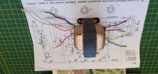
Although the passage of time is long, I vaguely remember receiving the Main Transformer and Output Transformers. Where these items were obtained from has been lost but I do remember that the Main Transformer came with complete wiring identification but the Output Transformer came with nothing. As an inexperienced young person, I did not consider requesting information from the supplier. I attempted to identify the primary and secondary winding by visual inspection and taking resistance measurements. As a result, I came to the conclusion that the
• Red and Black wires (13 ohms) were the secondary winding with the yellow and green as the centre tap.
• Red & Orange anode (1056 ohms), Blue and grey 20% feedback and white as centre tap of the primary
It was with these identifications that the construction was built way back 44 years ago. I now question whether this identification was correct?
If I was wrong, then it is likely that I have used the primary winding as the speaker output while the Secondary connection were connected to the anodes of the ECL82’s using the Blue & Grey connection as the 20% taps.
Have I got it wrong? If yes then the supplier supplied an output transformer without any 20% taps on the primary and the additional wires Blue and grey are simply different speaker impedance outputs.
Attached is an image of one of the transformers, is anyone able to offer advice.
Before I consider moving on, I would be very grateful for any comments regarding my identification of the wiring that took place some 44 years ago
At this point I made up my mind to dispose of the project and in June of 2021, plans were made to place it on eBay. While photographing it, I concentrated on the wiring from the tag board and there I thought I saw a possible cause of the problem.
Although the passage of time is long, I vaguely remember receiving the Main Transformer and Output Transformers. Where these items were obtained from has been lost but I do remember that the Main Transformer came with complete wiring identification but the Output Transformer came with nothing. As an inexperienced young person, I did not consider requesting information from the supplier. I attempted to identify the primary and secondary winding by visual inspection and taking resistance measurements. As a result, I came to the conclusion that the
• Red and Black wires (13 ohms) were the secondary winding with the yellow and green as the centre tap.
• Red & Orange anode (1056 ohms), Blue and grey 20% feedback and white as centre tap of the primary
It was with these identifications that the construction was built way back 44 years ago. I now question whether this identification was correct?
If I was wrong, then it is likely that I have used the primary winding as the speaker output while the Secondary connection were connected to the anodes of the ECL82’s using the Blue & Grey connection as the 20% taps.
Have I got it wrong? If yes then the supplier supplied an output transformer without any 20% taps on the primary and the additional wires Blue and grey are simply different speaker impedance outputs.
Attached is an image of one of the transformers, is anyone able to offer advice.
Before I consider moving on, I would be very grateful for any comments regarding my identification of the wiring that took place some 44 years ago
Attachments
You can easily determine whether the mystery (feedback?) winding is connected to the primary or secondary or neither. Need to recheck your measurements - primary winding could be over 1000 Ohms, but that's a lot. The secondary needs to be a tenth of your number, or less.
The original oscillation could have been having the polarity wrong for feedback - only one polarity is correct; the other oscillates.
All good fortune,
Chris
The original oscillation could have been having the polarity wrong for feedback - only one polarity is correct; the other oscillates.
All good fortune,
Chris
Maybe you have an output transformer with a 70V or 100V PA winding (red+black)? As Chris says, 13 ohms for a secondary is very high, usually less than an ohm. Can you give resistances between black/red/yellow/green?
Hi Chris and Tikiroo
Many thanks for taking the time to reply to my post.
The two transformers were purchased specifically for The Mullard Seven -watt Stereophonic Amplifier. The “Mullard Circuits for Audio Amplifiers “booklet listed a range of suitable transformers. Although I cannot remember which Manufacturer/ Type number I purchased or which supplier supplied the items, I am sure I would have requested the correct item. However, what the supplier did delivered I cannot be certain off. As stated, the two came with no indication of model or wiring layout. This happened some 44 years ago hence my confusion now.
Chris, you commented on the primary windings high resistance reading and Tikiroo you mentioned that you would expect the secondary reading to be low. Both your comments lead me to believe that 44 years ago, I did correctly identify the secondary and primary windings and this was how the transformers were wired up. So, my thoughts that I had incorrectly identified the Secondary and Primary coils were wrong.
This in effect means that the source of the problem must seated somewhere else.
To answer your questions, I have attached indication of a complete set of resistance reading taken from both coils.
Chris, yes, I did check that the feedback loop was taken from the correct side of the secondary coil.
With many thanks and
Regards
Brian Odurny
Apply a low AC voltage across the primary and measure all other voltages.
This will allow you to calculate the turns ratios.
This will allow you to calculate the turns ratios.
Just a few late night thoughts:
Do you have a schematic? I'm not familiar with the Mullard seven.
Most likely it has negative feedback from the opt secondary. Get the polarity wrong and it becomes positive feedback = oscillator. Usually high frequency, but if it is too high to hear it could result in overloading the power supply leading to low frequency pulses? You need a scope.
Disconnect the feedback to see if it gets stable.
Also, amps from those era are way too sensitive for today's sources. You may want to change the design for less gain.
About the secondary lead resistance: did you take into account the resistance of the test leads? Also, a little oxide on the transformer leads could add a few ohms to the measurements.
a complete set of resistance reading taken from both coils.
Chris, yes, I did check that the feedback loop was taken from the correct side of the secondary coil.
Well, not really complete. You may well find that the blue and gray of your primary windings are the plate connections and the red and orange are the screen taps, but can't tell without all windings measured.
We can't really say that there's a "correct" side of the secondary, because that depends on the polarity of the primary's connection.
This looks to be a pretty fancy transformer, possibly with twin stacks of interleaved windings side-by-side, and identical secondaries brought out and intended to be paralleled. The measured resistances are still pretty high, but not impossible. You'll need to test with AC to get their relative polarities, and the primary - secondary polarity.
All good fortune,
Chris
Hi Russc: thanks for the suggestion. I am in the process of obtaining a low voltage AC supply. As part of a “Down Sizing exercise “I have just disposed of 44 years of electronic components never thinking I would ever need them again. A moment of madness!
Parafeed813: Have attached a schematic for your perusal. I have checked and rechecked the phase of the feedback loop many times. Get it wrong and yes it does go into positive feedback and is totally different to the instability I get when the feedback loop is connected as it is supposed to be. Thanks for the suggestion of taking into account the resistance of the meter leads. Very lapse of me.
Chris: Many thanks for your input. I must say that I never considered that the blue and grey leads might be the anode connections. The resistance across the blue and grey leads is 218 ohms considerably less than that of the red and orange leads. However, I have tended to be guided by the schematic of a transformer where the 20% taps are shown more towards the centre tap. Of course, this again show how the lack of any detailed information when the items were supplied has caused issues through the years. You also raised another issue which is interesting. That is the relationship of the primary windings to that of the secondary winding in terms of polarity. Need to give that some thought. Finally, I know little about paralleled windings again without details it may be difficult to resolve. As I mentioned to Russc, I will carry out some low voltage AC tests. With this and a little maths I should be able to learn a lot more about the Transformer.
Due to the great support, I have received through this forum, I have now decided to carry out a full rebuild of the amplifier using a new chassis, tag boards valve holders and some resistors. That’s assuming that I can resolve the full identification of the two transformers I have
Many thanks to you all
kind regards
Brian
- Home
- Amplifiers
- Tubes / Valves
- A 44 year build of The Mullard Seven -watt Stereophonic Amplifier.