I inserted a Thermistor (Amphenol CL-60) in between the power transformer 550V secondary and the 83 tube rectifier (see schematic below).
Typical turn on sequence is as follows:
1. flip Switch #1 to turn on 120Vac to the power amp. This sends the appropropriate Vac to each of the tube filaments, but not the B+.
2. Wait 30+ seconds as the filaments come up to speed
3. flip Switch #2 to send 550Vac to the 83 rectifier and thru the power supply
The thermistor was supposed to slowly ramp up the current and thus avoid the loud "pop" caused by the current surge. Unfortunately, the current surge is still there and so is the "pop" noise.
Why is the pop still occuring? Thoughts?
Attachments
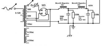
However the thermistor is supposed to work, it is now only affecting one of two connections to the 83 (or 5Z3). The other connection will make the 83 (or 5Z3) work as a half wave rectifier as soon as you flip switch #2.
Maybe a cold solder somewhere. Happen to me on 1 channel so I resoldered all the points then it fixed. Check the coupling caps too.
The switch and thermistor should be on the center tap ... like it is now you have allways half wave rectified +B . Not sure if a thermistor can cure the issue but do it right . When the tubes are heted of course they are very sensitive to any voltage change ... like applying delayed +B
Last edited:
Going from zero current to suddenly any amount is going to produce a pop. You'd be better off switching the speakers if this is an SE amp.
flip Switch #2 to send 550Vac to the 83 rectifier and thru the power supply.
Unless switch #2 is rated for 630VAC, remove it immediately.
The two-switch solution works better when you use two separate transformers, one for the filaments (and bias voltages if present) and one for the B+, and the switches can then both be rated for line voltage.
I never have pop problems but I have the b+ come on same time as everything else. The rectifiers start conducting as the filaments get hot, a second or so. Slow enough so there is no pop. I guess the power tubes are coming on slowly as well and everything just starts working. The only reason to delay the B+ is if your electrolytics cant handle the no load voltage rails. So get new electrolytics w higher ratings...
Update: I have monoblocks. On the left channel I put the thermistor in between the wall AC and the power transformer (common). Also, the filament and B+ are turned on together / simultaneously. This works well. No more pop.
On the right channel, my toggle switch shorted (positive to negative) and I believe this fried my power transformer. Fudge!!!! I need to do some testing. More to come. Damn.
On the right channel, my toggle switch shorted (positive to negative) and I believe this fried my power transformer. Fudge!!!! I need to do some testing. More to come. Damn.
banpuku,
Your schematic, Post # 1, shows the part you added, is in series with only 1 plate.
Instead, put the part in series between the rectifier output, and the first filter choke.
I believe the purpose of a thermistor is to have a resistance that is proportional to ambient temperature.
Example:
Old 6 transistor battery powered radios had a thermistor in the bias circuit of the push pull output transistors, to keep them from thermal runaway when the ambient temperature was hot.
If you want to reduce power supply inrush current, then use the correct part, one that is specifically made to limit inrush current.
And my poor memory at my age, prevents me from telling the name of that kind of part.
Last edited:
Yes, you used it wrong to begin with, as 6A3 says.
To boot, you only said "CL60" but not its value.
Typical is 10 ohm, which will do NOTHING there.
Highest available is 120 0hm (per Mouser catalog) and it won´t do much, if at all.
Once parts are hot and conducting, any switching will intoduce a voltage/current jump, hence potentiallly a POP/Thump; I´d forgo Standby and just let amp wake up the normal way.
agreed that the standby switch will be removed. Now, I am fighting with the power transformer on the right monoblock. There was smoke coming from the amp, so I immediately shut down. It was wired just like the other monoblock (I think) that is working well. So, what is the best way to test the power transformer?
I measured the resistance on both monoblock's primary and they both measured = 1.5ohm. The secondary on both monoblock's measured 150ohms. Is there another measurement I should do on the suspect power transformer?
I measured the resistance on both monoblock's primary and they both measured = 1.5ohm. The secondary on both monoblock's measured 150ohms. Is there another measurement I should do on the suspect power transformer?
Check your 10uF 600V Electrolytic capacitor.
500VAC = 700V peak.
You are using a choke input supply (0.9 x RMS 500 x 0.9 = 450V). And there is the 5Z3 rectifier drop, that reduces the B+ even more.
But that works only when the power supply is loaded.
Without a load, a choke input supply does not have Critical Inductance, so the B+ rises to Peak value.
The B+ is Un-loaded at power up, by the cold output tubes, the B+ will rise to 700V - 5Z3 drop voltage, 58V at 225mA (and is much less than 58V when there is no load).
700V - 58V = 642V, or more likely 700V - 20V or 30V, is much more than your 600V electrolytic rating.
(The 5Z3 will drop much less than 58V until the electrolytic gets over hot from the Un-loaded power supply, and starts to destroy itself.
Two 20uF 600V caps in series, with a resistor across each cap, will divide the voltage properly, and act as a bleeder too.
That is just my opinion.
Last edited:
agreed that the standby switch will be removed. Now, I am fighting with the power transformer on the right monoblock. There was smoke coming from the amp, so I immediately shut down. It was wired just like the other monoblock (I think) that is working well. So, what is the best way to test the power transformer?
I measured the resistance on both monoblock's primary and they both measured = 1.5ohm. The secondary on both monoblock's measured 150ohms. Is there another measurement I should do on the suspect power transformer?
To see whether you have shorted turns or similar heavy lossy damage, turn amp on through a lamp bulb limiter, bulb between 50-100W, and all secondaries disconnected (and taped for safety).
Normal would be for bulb to blink, because of initial magnetizing current, and then dimming down to dark orange, red or even almost invisible, that means your transformer is healthy.
If it stays bright range or yellow, then there´s something inside wasting energy, which will overheat transformer if straight to mains, not a good situation.
If filament shines orange but not too bright and you want to be 100% certain, plug primary into mains but still fused, of course, and check: does it buzz too much?
Wait 15 minutes: did it barely warm up or is it becoming uncomfortably hot?
My tests amout to the poor Man´s watt meter he he.
If you have a Kill-a-Watt by all means use it 🙂
Update: I must have had a short circuit on the right monoblock which cause the short. I rewired the power supply and all is good. Got rid of the filament toggle switch and now both the filament & B+ are turning on simultaneously with no pop. Yea!
I am not a transformer expert. There are far more knowledgeable people than me on this forum who could suggest a better way of testing. Smoke is never good and a damaged transformer may well fail some time down the line. But seeing as you have 2, I would consider removing all the tubes from each amp and turn on both amps and check the temperature rise of each power transformer, and if you can safely, monitor the current draw into each amplifier. Do you have suitable mains inlet fuses?
Update: The reason the right monoblock was not working (including smoke) was because a pair of wires had the sheath melt while soldering. This caused the pair to touch and short out. The smoke was the wire sheath.
All is well after resoldering and changing the faulty pair of wires.
All is well after resoldering and changing the faulty pair of wires.

- Home
- Amplifiers
- Tubes / Valves
- Inserted a Thermistor and still getting a pop sound