Good morning. Thank you for accepting me into the forum.
My beloved CD304 Mk1 is having some issues. I remember buying it new in the mid 80's from Lasky's in Tottenham Court Road, London, costing about £350. Everything about it is original, apart from a new drive belt.
Anyway, as the title suggests, I am getting no sound - most of the time.
Sometimes a CD will play straight away for a few minutes, make a popping noise, and then nothing, although the laser seems to be still reading the CD, as the tracks still display, and the track time still increases, until the next track, and keeps going, but no sound.
Sometimes a CD will not play for a few minutes, and then randomly start playing, usually the whole way through, although longer CD's will start to have reading issues towards the end.
I am a bit geeky, so have read through articles on the internet, and have tried a few things, like prodding and flexing the two back-to-back boards with a pencil end whilst playing a CD. Nothing has materialised.
I have also read that the blue Philips capacitors can be the culprit. I have done much soldering over the years, so am happy to do that, but cannot find a definitive list of which capacitors to buy - is there such a thing?
Any ideas would be much appreciated. Thank you.
I am no expert in these matters but it sounds to me like it could be the laser and/or the voltage going to the laser. I have modded a few Sony PS1s and one of those does what your player does and will not play some CDs all the way through and it will not play CDRs.
In which part of the circuit are the blue Philips capacitors located?
Rob.
In which part of the circuit are the blue Philips capacitors located?
Rob.
I believe one is the decoding board. Not sure about the other. Possibly servo board.I am no expert in these matters but it sounds to me like it could be the laser and/or the voltage going to the laser. I have modded a few Sony PS1s and one of those does what your player does and will not play some CDs all the way through and it will not play CDRs.
In which part of the circuit are the blue Philips capacitors located?
Rob.
As you describe the issue first you should check for bad/intermitent connections , pull out and reinsert all the connectors .Or bad solders joints on the board , applying preasure with a finger in different parts on the board while playing could make the sound appear / disappear in this case .
I will check all connectors. I have flexed the boards, and I cannot make the sound appear, even momentarily. I have also been reading about the through board grommets failing. So, something else to look at.As you describe the issue first you should check for bad/intermitent connections , pull out and reinsert all the connectors .Or bad solders joints on the board , applying preasure with a finger in different parts on the board while playing could make the sound appear / disappear in this case .
Hi,
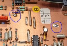
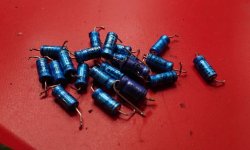
I've reworked several Philips CD over the years, and in particular the 304 MKI and II show the same illness after a time. Besides the blue caps (I recommend Panasonic FA and/or Elna Silmic, throw the blue stuff far away) the culprit often is the connection between upper and lower side. Best is to put a piece of blank wire through the hole and resolder it on both sides.
When you take this old guy apart, it's the perfect time to replace especially the 5V regulator with a 2A-type, as the original one's running on the edge. Servo-and Laser-current should be adjusted after replacing all caps and regulators. Clean all trimmers before re-adjusting or just replace with new ones.
BTW: never found a failure on the 4385 🙄 flying wires going through the chassis.
Some pictures below (including NOS-conversion)
Attachments


Last edited:
Hi,
I've reworked several Philips CD over the years, and in particular the 304 MKI and II show the same illness after a time. Besides the blue caps (I recommend Panasonic FA and/or Elna Silmic, throw the blue stuff far away) the culprit often is the connection between upper and lower side. Best is to put a piece of blank wire through the hole and resolder it on both sides.
When you take this old guy apart, it's the perfect time to replace especially the 5V regulator with a 2A-type, as the original one's running on the edge. Servo-and Laser-current should be adjusted after replacing all caps and regulators. Clean all trimmers before re-adjusting or just replace with new ones.
BTW: never found a failure on the 4385 🙄 flying wires going through the chassis.
Some pictures below (including NOS-conversion)
Some of that seems quite complicated. Like for like replacement I can do, but not sure I have the knowledge to make the adjustments. I will start with the through grommets and go from there. But, really appreciate your help.
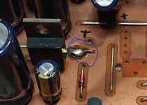
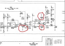
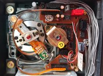
Many of the small electrolytic caps could be quite deteriorated by now but these 33uF caps are prone to trouble and located in the laser power circuit. They are just 3 of many though.
I would advise against altering ANY preset control unless you know exactly what you are doing and have the means to correctly align them.
As always an oscilloscope is your key diagnostic tool.
I would advise against altering ANY preset control unless you know exactly what you are doing and have the means to correctly align them.
As always an oscilloscope is your key diagnostic tool.
Attachments
That's a very important advise. Especially everything regarding the laser and its PCB has to be handled with extreme care. You should also never disconnect the laser without ESD-equipment.
However, you can find the caps Mooly mentioned in the picture below. The golden ones.
However, you can find the caps Mooly mentioned in the picture below. The golden ones.
Attachments
Haven't used an oscilloscope in over 40 years, so won't be touching any presets. I will be going basic.Many of the small electrolytic caps could be quite deteriorated by now but these 33uF caps are prone to trouble and located in the laser power circuit. They are just 3 of many though.
I would advise against altering ANY preset control unless you know exactly what you are doing and have the means to correctly align them.
As always an oscilloscope is your key diagnostic tool.
Many of the small electrolytic caps could be quite deteriorated by now but these 33uF caps are prone to trouble and located in the laser power circuit. They are just 3 of many though.
I would advise against altering ANY preset control unless you know exactly what you are doing and have the means to correctly align them.
As always an oscilloscope is your key diagnostic tool.
That's a very important advise. Especially everything regarding the laser and its PCB has to be handled with extreme care. You should also never disconnect the laser without ESD-equipment.
However, you can find the caps Mooly mentioned in the picture below. The golden ones.
I might be changing them if easily accessible. The player sat in storage, unused, for 18 years, so pretty sure all the electrolytics are knackered.
They should be easy to replace but beware of the solid core wire used by Philips as it can fracture with repeated bending. I would disconnect any plugs on those boards to work on them and that includes the lasers flexiprint connector. Those are easy to remove/replace as long as you only ever apply vertical forces to them Do not bend them.
Be aware of static with the laser but if normal precautions are taken there is no issue. Just touch the main board chassis/circuitry first and then remove the connector. Touch the main board chassis/circuitry again before replacing the connector.
Be aware of static with the laser but if normal precautions are taken there is no issue. Just touch the main board chassis/circuitry first and then remove the connector. Touch the main board chassis/circuitry again before replacing the connector.
I appreciate the assistance. I will do this one step at a time, testing along the way.They should be easy to replace but beware of the solid core wire used by Philips as it can fracture with repeated bending. I would disconnect any plugs on those boards to work on them and that includes the lasers flexiprint connector. Those are easy to remove/replace as long as you only ever apply vertical forces to them Do not bend them.
Be aware of static with the laser but if normal precautions are taken there is no issue. Just touch the main board chassis/circuitry first and then remove the connector. Touch the main board chassis/circuitry again before replacing the connector.
Success - fingers crossed
Well. Bit of an update. I held my breath and took apart the CD304 once again. This time removing the two back-to-back boards from the main body of the deck, taking pictures of the connections before I did it.
Armed with soldering iron, solder sucker and some thin wire trimmed off some old component legs, I religiously replaced the board grommets or griplets on both boards. I didn't have to drill through the board, as I was able to pass the wire through the board, after removing the solder. I then re-soldered the wire in place.
I wasn't expecting it to work, but after I put it all back together and tested with some headphones, I couldn't believe it - there was sound. I will replace the capacitors at some point, but it all sounds great at the moment - listening to Rush, Moving Pictures at the moment. The big test will be a 70 minute CD, which always seemed to fail at about 50 minutes.
Thank you all.
Very chuffed with myself. A sense of achievement after months of frustration. Just made it through an 80 minute CD.Well doneyou sound to be getting there.
Now if I can just get my NAD 3030 back from where it is, and working, I will be really happy. That's another sad story. I wonder if I will ever see it again.
Perfect work, congrats! Another old Philips back in the saddle again 😎
Regarding the NAD: Now the soldering iron is hot, just grab a kit of a F6 or similar, then a B1 or BA2018 in front and you're done. Just a few hours of fingerwork 😀.
Regarding the NAD: Now the soldering iron is hot, just grab a kit of a F6 or similar, then a B1 or BA2018 in front and you're done. Just a few hours of fingerwork 😀.
Last edited:
Wish I could. I sent it off for repair to someone who was recommended to me last November. I talk to him periodically and then he disappears for weeks. Stresses me out. I did say I was in no hurry, but.....Perfect work, congrats! Another old Philips back in the saddle again 😎
Regarding the NAD: Now the soldering iron is hot, just grab a kit of a F6 or similar, then a B1 or BA2018 in front and you're done. Just a few hours of fingerwork 😀.
I will replace the capacitors at some point
I recently recapped a B&O CDX which also uses the cdm-1 and has very similar board layout using the Philips caps. Every single one of them was significantly out of spec.
- Home
- Source & Line
- Digital Source
- Philips CD304 Mk1 - No sound