Hi folks
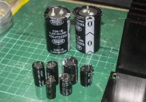
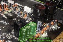
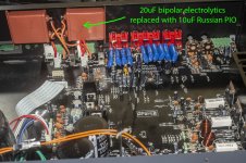
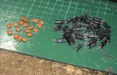
My Apart Concept1 amp started sounding distorted a couple of weeks ago, so I replaced all the large electrolytics and it cured the issue, I suspect the three caps next to the voltage regulator heatsinks had dried out.
However, there is still a problem, the amp has four inputs labelled A, B, C & D. It works great on B, C & D but A sounds distorted.
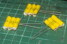
I also changed the 2.2uF electrolytic caps on the inputs to 2.2uF polyester ones, I don't have a service manual or a schematic, otherwise I'd replace all the caps in the signal path.
So, anyone got any bright ideas as to how to diagnose and fix input A? The only thing I can think of is to trace the channel from the input jacks, replacing all the caps along the way. However, I'm dubious that just a change of caps will do the job as the other 3 channels sound fine.
My Apart Concept1 amp started sounding distorted a couple of weeks ago, so I replaced all the large electrolytics and it cured the issue, I suspect the three caps next to the voltage regulator heatsinks had dried out.
However, there is still a problem, the amp has four inputs labelled A, B, C & D. It works great on B, C & D but A sounds distorted.
I also changed the 2.2uF electrolytic caps on the inputs to 2.2uF polyester ones, I don't have a service manual or a schematic, otherwise I'd replace all the caps in the signal path.
So, anyone got any bright ideas as to how to diagnose and fix input A? The only thing I can think of is to trace the channel from the input jacks, replacing all the caps along the way. However, I'm dubious that just a change of caps will do the job as the other 3 channels sound fine.
Attachments
Last edited:
How is the source selected, by mechanical switch, or analog switch, relay, etc?
Could be a capacitor or a bad connection.
Could be a capacitor or a bad connection.
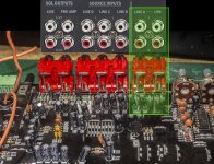
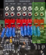
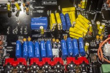
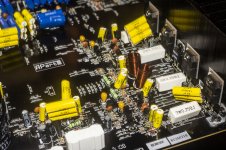
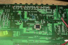
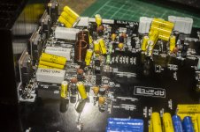
It's all digital as far as I can tell and it says on the front 'Digital Controlled Amplifier'. The main pcb has the inputs at the back then the rst of the board is taken up by the power supply on the left and the power amp on the right. There's another PCB mounted on the front panel that has a microprocessor and I think that PCB is where the switching is done, there are several multiple wire connectors between the two PCBs. I shall take some more pics of the whole thing tomorrow in daylight. Not having a service manual is a PITA.
Last edited:
Then the first thing would be reflowing the relevant IC solder connections.
That is a common problem with reflowed pcbs, developing bad solder joints.
If you can follow the bad signal to the IC, just solder that one pin.
Look on the IC data sheet, that should be all you need.
That is a common problem with reflowed pcbs, developing bad solder joints.
If you can follow the bad signal to the IC, just solder that one pin.
Look on the IC data sheet, that should be all you need.
Last edited:
Cheers that's helpful. I shall take it apart tomorrow and trace the signal from the A input across the main PCB to the connector to the control PCB and resolder all the joints along that path, then I can pull the control PCB and find out what IC is responsible for controlling things and repeat the resoldering on that PCB. I'll probably replace some of the caps as well as there are no polyester or polypropylene caps in this amp, it's all electrolytics and ceramic disks.
Don't replace any ceramic capacitors associated with digital (or even analog) ICs,
because these ceramic capacitors are essential for proper operation.
They have very specific purposes that film capacitors cannot preform.
because these ceramic capacitors are essential for proper operation.
They have very specific purposes that film capacitors cannot preform.
Last edited:
Oh, no, I was only thinking of replacing those on the main PCB, mainly those that are in the signal path, I won't touch the control PCB, as long as that works, I'll not fiddle with it beyond resoldering any cold joints.
But thanks for the tip though, always much appreciated.
But thanks for the tip though, always much appreciated.
Well, I've spent the weekend working on the thing and made no improvement, Inputs B, C & D work fine, A is badly distorted. I think it's the IC itself that is faulty. I replaced all the caps with polyester & tantalum, but I don't think it sounds any different. I also changed the power socket from a 2-pin to a 3-pin with a built-in noise filter.
I'll keep this amp in service until I either build a replacement or buy something to modify.
I'll keep this amp in service until I either build a replacement or buy something to modify.
Attachments
-
 DSC00598.jpg354.3 KB · Views: 194
 -
 DSC00592.jpg353.7 KB · Views: 161
 -
 DSC00590.jpg328.7 KB · Views: 179
 -
 DSC00589.jpg294.5 KB · Views: 156
 -
 DSC00588.jpg231.6 KB · Views: 161
 -
 DSC00587b.jpg338.5 KB · Views: 188
 -
 DSC00587.jpg354.2 KB · Views: 214
 -
 DSC00585.jpg471.5 KB · Views: 224
 -
 DSC00584.jpg182.5 KB · Views: 179
 -
 DSC00597.jpg283.3 KB · Views: 194
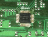
Check on the data sheet, the IC is a 6 channel selector and volume control.
Short or swap the connections from A and B to check.
It is still available, so not exotic.
Another trick I have seen is to brush a small quantity of flux on it, and flow all the joints with a SMD heat source, or you could use the solder paste used to bond SMD to tracks.
The solder paste is powdered solder and flux in a paste like consistency, used a lot for cell phone repair, among other purposes.
Clean off later, and see the result.
After an hour or so of use, the amp has died, it now displays 'Amplifier Error'.
I think that IC has died, sadly.
I think that IC has died, sadly.
That is a selector.
See if you can select inputs.
And if you need to check, just short it out, from needed in to out, see if the sound comes back.
It could be an issue in the power amp section, if both channels are dead then maybe this selector is bad.
You can select 3 stereo inputs?
See if you can select inputs.
And if you need to check, just short it out, from needed in to out, see if the sound comes back.
It could be an issue in the power amp section, if both channels are dead then maybe this selector is bad.
You can select 3 stereo inputs?
It just constantly displays 'Amplifier Error' on the display now, nothing functions, no sound, hence I think the IC is dead.
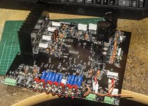
That's the problem, no service manual available. I've stripped the amp down to it's chassis and am going to use it to house a B1 buffer based preamp which I've built but needed a housing for. I was using the Apart amp as my preamp, so it's achieving the same result as repairing the amp.
The amp has a pre amp and a main amp?
Disconnect the supply to the main amp, power up, see if the message is still displayed.
Or else junk the innards, or keep aside in your hoard, like I do...
Disconnect the supply to the main amp, power up, see if the message is still displayed.
Or else junk the innards, or keep aside in your hoard, like I do...
It's an integrated amp so has pre and power sections, but all on one PCB so not separable. It has a line out that can be used to connect a power amp, which is how I was using it - biamping a pair of speakers using this amp with a power amp connected to it.
I've stripped it down, unsoldered any useful parts and reused the chassis, so my hoard of spare parts has been boosted and the chassis has been ideal to house my B1 buffer preamp project, so no great loss as I paid just 15ukp for this amp last year, had a year or so use out of it and the spare parts and chassis it has now provided would cost much more than 15ukp so it's all worked out okay.
I've stripped it down, unsoldered any useful parts and reused the chassis, so my hoard of spare parts has been boosted and the chassis has been ideal to house my B1 buffer preamp project, so no great loss as I paid just 15ukp for this amp last year, had a year or so use out of it and the spare parts and chassis it has now provided would cost much more than 15ukp so it's all worked out okay.
The amp section was not in use, why were you using another amp?
Anyway, this one has had its life over...
Anyway, this one has had its life over...
The amp section was in use, as I said, I was bi-amping my speakers, four channels - two left, two right, two of the channels were powered by this amp, two by the other amp.
I'm in the process of upgrading to tri-amping using a 3-way active crossover instead of the passive 2-way crossovers in the speakers.
I'm in the process of upgrading to tri-amping using a 3-way active crossover instead of the passive 2-way crossovers in the speakers.
- Home
- Amplifiers
- Solid State
- Apart Concept1 Repair