Hi Guys, Hi Perry - long time no see ;-)
I have a 2 ch. amp that has a semi "dual" smps. that means 2 transoformers , driven by 4 banks of mosfets. if I connect all 4 mosfet banks without the transformers all looks fine on the oszi, the "dual" banks are driven by two driver transistors.
The "outside" of both lines is in parallel, so if only one transformer is connected it supplies all channels with outside voltage, dre outputs work fine as well as the filters, etc.
If i connect the 2nd transformer input coils the amp still works, if i connect one of the 2nd trans output coils to the rectifiers it still works, if I connect the 2nd output coil of the 2nd trans the amp goes into protect. Currently I rewinded the 2nd trans output coils, waiting for the result..... any Ideas besides a short in the 2nd trans output coils ? the rectifiers are ok and the amps , filters, etc are all ok. any other idea in case the new coils would cause the same issue?
With only the last set of secondary windings disconnected, measure the AC voltage across the output of the 3 connected secondary windings and also the disconnected pair of windings. Do they all read approximately the same?
Unless the windings are shorted primary to secondary, it's not likely to be a shorted winding. If you short a turn on either the primary or secondary, it will act like a dead short when you try to drive it.
Unless the windings are shorted primary to secondary, it's not likely to be a shorted winding. If you short a turn on either the primary or secondary, it will act like a dead short when you try to drive it.
When connecting different windings in parallel,or DC outputs in very low impedance supplies (such as SMPS) any voltage difference between them, even if quite small will look like a shorted or partially shorted secondary.
In EI iron transformers, significant wire DC resistance makes small errors "forgivable" but not in tenths of an Ohm Ferrite ones.
Measure DC voltage output at each independent supply, those intended to work in parallel must be within millivolts, serious.
In EI iron transformers, significant wire DC resistance makes small errors "forgivable" but not in tenths of an Ohm Ferrite ones.
Measure DC voltage output at each independent supply, those intended to work in parallel must be within millivolts, serious.
Hi guys, thx for the help, well I could have saved my time for rewinding the transformer. At first I´d like to correct my first post, the amp does not go into protect, it starts drawing a lot of input current and my bench power supply is then going into protect.
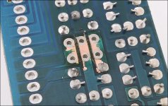
So after rewinding the transformer the same behaviour, all fets in, rectifiers in, all works until I connect the second output coil to the board. ....well..... so I simply checked an ohmmeter, there is as short between the solder place where the coil output goes and ground. Have you ever seen this ? I know it´s a double sided board but i even cut the line and it still reads 0 ohms between the ground and the coil output place. Isn´t this weird ? Could it really be the throuput points in the curcuit board are melted together?
So after rewinding the transformer the same behaviour, all fets in, rectifiers in, all works until I connect the second output coil to the board. ....well..... so I simply checked an ohmmeter, there is as short between the solder place where the coil output goes and ground. Have you ever seen this ? I know it´s a double sided board but i even cut the line and it still reads 0 ohms between the ground and the coil output place. Isn´t this weird ? Could it really be the throuput points in the curcuit board are melted together?


so it seems I cannot use the original solder point anymore, what gauge should I use then for connecting the transformer output coil directly to the rectifiers ? Do you think AWG13 /2,5mm2 will be strong enough?
yes, recs. removed but still see 0 ohms. Also cleaned all old solder from both sides, still 0 ohms.
I´ve never seen smthg like this before, even I have not fixed as many amps as you but there have been quite a few 🙂
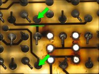
If I put a LED flashlight on the spot I can see a little shodow inside the curcuit board between the two solder points. Maybe a production error.
Just connected the 2nd output coil via a wire to the rectifiers and the smps works like a charm 🙂 so what do you think, 2.5 sqare mm should be alright?
I´ve never seen smthg like this before, even I have not fixed as many amps as you but there have been quite a few 🙂
If I put a LED flashlight on the spot I can see a little shodow inside the curcuit board between the two solder points. Maybe a production error.
Just connected the 2nd output coil via a wire to the rectifiers and the smps works like a charm 🙂 so what do you think, 2.5 sqare mm should be alright?
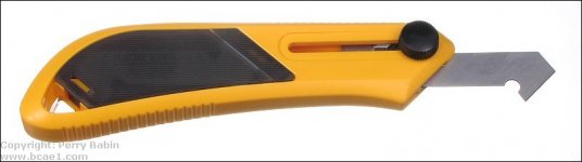
You can cut the board between the traces. The easiest way I've found is to use an acrylic scoring tool. Any thin cutter will work.
The boards can become conductive. It's' common where there is excessive heating. Driver boards in some amps had a LOT of this problem.
When removing the material from the board, you have to remove 100% of the darkened material.
If you don't cut the board, you'll have to cut the traces connected to that pad.
Attachments
I think I will go with the cut traces and use a wire directly between the transformer coil and the part where the rectifiers are soldered in, there´s quite a large spot where i can put lots of solder on to guarantee a very good connection. Thx again Perry, u r the best ;-)
Last edited:
I had something similar happen on a spa controller board. It had gotten wet and shorted out pretty dramatically, enough to bur a hole through the pcb. At first I tried repairing it with jumper wires and some copper sheet. But when I went to check it two traces that should have been completed so separate weren't. The only thing I could figure out was something within the layers of the board was making a connection. Ended up moving part of the circuit to a new board I made.
- Home
- General Interest
- Car Audio
- SMPS question , sry guys I dont get it