Hello, i have a friend that gave me an old kenwood kr 3400 from the 70´s. i liked the sound and since is a simple to get the main boards out and i had caps at home, i made a recap on the power supply and on the main board after i dowloaded the schematic.
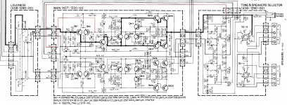
When i looked at the schematic i found the the bass and treble controls are connected to the negative feedback of the amp. i´m trying to find a way to disconnet them to bypass the tone control pots but i need some help.
I don´t know if i took off the first input 6.8uf cap and the 6.8uf output cap from the tone controls block will to the trick.
i tried only disconnect the negative feedback pin 5 and 6 on the main amp and i have more gain and also litle noise mixed with music.
the ideia is to bypass the tone controls and maintaining the amp linear.
thanks.
Attachments
I guess you could figure out what the DC equivalent is for the controls centered, but why mess with a circuit that works?
If it were mine, I would upgrade the tone control components and leave them in. There is no extra gain stage involved, so no real advantage in bypassing them. That, and this amplifier is good, but not good enough to really worry about any supposed increase in sound quality. If you upgrade the tone control components, there will be no sound quality increase. Any level differences are swamped by the ones in the volume control - so also not a concern.
I repair and upgrade audio equipment for a living. I would advise you as a customer to do the same thing. Upgrade it and enjoy it.
-Chris
Thanks Chris, i think i will follow your advice, upgrade the tone control capacitors and use it. I also like to sometimes adjust a little treble and a little bass.
the ideia was to see how the amplifier would sound without them...
the ideia was to see how the amplifier would sound without them...
if you disconnect the cap 425,426.
the gain would be too high,
you can pair a 5.1k resistor to the Re15 and R16.
this will lower the gain,
if still too high you can use 3.9k, or 2.7k.
why not just center the treble and bass knobs to have a flat response.
the gain would be too high,
you can pair a 5.1k resistor to the Re15 and R16.
this will lower the gain,
if still too high you can use 3.9k, or 2.7k.
why not just center the treble and bass knobs to have a flat response.
Hi pistollero,
It would sound the same, and have the same amount of distortion (from experience).
Tone controls are not evil. I have an expensive set up and it has tone controls. I don't use them often, but sometimes they can save the day.
Enjoy your system! IT should sound pretty good, and your speakers may limit how good this one will sound.
Best, Chris
Ok, thank you for the advices. i will upgrade the caps on the tone controls and stay with them.. i also will upgrade the internal wiring to the speakers.. i think some wiring is not even copper..
Hi pistollero,
Little to no advantage in upgrading the wire, but it won't hurt anything either. Just make sure the sure runs exactly the same way (lead dress).
ENjoy!
Little to no advantage in upgrading the wire, but it won't hurt anything either. Just make sure the sure runs exactly the same way (lead dress).
ENjoy!
Remove (break red) the tone circuits from the input side of the amplifier. Solder 10 kΩ resistors in parallel with R15,16 (it is possible to pick up).
Regarding the transistors on main board, is the upgrade of them needed?
Newer parts sound better or should i maintain the old ones?
Newer parts sound better or should i maintain the old ones?
if you want to upgrade the amp and have good result,
one simple thing to do is to change the two 3300u 25v caps to 10000u 35v.
with a better power supply, sound is much alive.
don't forget to change the coupling caps too, with better quality caps.
one simple thing to do is to change the two 3300u 25v caps to 10000u 35v.
with a better power supply, sound is much alive.
don't forget to change the coupling caps too, with better quality caps.
i´ve changed both already, the psu for 6800uf each and input caps for 1uf film.
is 10000uf needed for such a low power amp?
is 10000uf needed for such a low power amp?
Hi pistollero,
I'm sorry, but I am going to have to strongly disagree with Alexchoi. Never greatly increase the size of filter capacitors. If you want, replace them with 4,700uF MAXIMUM. Higher voltage capacitors generally do have better characteristics - within reason! Finally, if the new part does not fit properly, you will cause more trouble than improvement. Never use parts that are too large for the mounting space.
The only large improvements you can gain will be with the input pairs - and they must be tightly matched. I designed a jig for this and gave the design to the DIYAudio community. If you can't match them tightly, do not touch them.
Another improvement might be possible. Some new output transistors have a flatter gain vs current characteristic. However, sometimes you need to re-compensate the amplifier when you change output transistor types. You need experience and test equipment for this. The change will be slight, if at all audible. Take reports of massive positive changes with a grain of salt. Common sense is your friend here.
One last comment on large capacitors. Increasing the size of filter capacitors greatly, massively increases the current spikes to charge the capacitors. That is because you are reducing the conduction angle of the diodes, and the current increase will astound you. This also increases the generation of high frequency spikes and noise. This type of noise is poorly rejected and can create issues above your hearing that can cause the sound to become "not clear". Using a fast recovery rectifier only makes this problem worse. Generally speaking, today's capacitors are better, so merely replacing the old ones with the same value will possibly improve things. Last point, if the original capacitors are "snap fit", the replacements should be as well. Those terminals are superior to the less expensive leaded types. So replacing a capacitor with normal wire leads with a snap type is also an improvement. But again, the new parts must properly fit in order for you to use them.
-Chris
Hi pistollero,
6,800uF is really not ideal. Replace the rectifiers with a normal characteristic (nothing fancy) for higher current ones to handle the peak surge currents.
The larger a filter capacitor gets, the more inductive it is and the less well it responds to fast current spikes. There are optimal sizes for each use and deviating from that means the filters perform less well. Higher capacitance is not better as a rule of thumb.
Most "modifiers" do not come from a technical background and do not posses the equipment needed to actually observe the effects of the changes they make. Most of their knowledge is based on what others report on the 'net, and those are based on expectation bias and wishful thinking. Very little being factual. Listening tests are really not accurate unless there are large problems.
For example, when I modify something I take "as found" readings, and when done I take the after readings. These are a spectrum of the output of an audio piece that does show noise floor and power supply noise.
Replacing parts is always a balance of conflicting parameters. Exaggerated component choices will never result in the best performance. You've go 6,800 uF in there. If they fit properly, leave them. If they don't fit, reduce the value to something that does. Do not increase the values any further.
-Chris
Hello, the 6800uf fit perfectly, i used them because was what i had at home and hand. i´m not fan of changing the original values also. On the main amp board, all capacitor value stayed the same as original ones.
regarding the input transistor pairs, i can pair them because i have a peak atlas dca pro that a bought recently. Just i don´t know what i use instead of the 2sa620 that came on q1-q4.
regarding the input transistor pairs, i can pair them because i have a peak atlas dca pro that a bought recently. Just i don´t know what i use instead of the 2sa620 that came on q1-q4.
Hi pistollero,
6,800uF is really not ideal. Replace the rectifiers with a normal characteristic (nothing fancy) for higher current ones to handle the peak surge currents.
The larger a filter capacitor gets, the more inductive it is and the less well it responds to fast current spikes. There are optimal sizes for each use and deviating from that means the filters perform less well. Higher capacitance is not better as a rule of thumb.
Most "modifiers" do not come from a technical background and do not posses the equipment needed to actually observe the effects of the changes they make. Most of their knowledge is based on what others report on the 'net, and those are based on expectation bias and wishful thinking. Very little being factual. Listening tests are really not accurate unless there are large problems.
For example, when I modify something I take "as found" readings, and when done I take the after readings. These are a spectrum of the output of an audio piece that does show noise floor and power supply noise.
Replacing parts is always a balance of conflicting parameters. Exaggerated component choices will never result in the best performance. You've go 6,800 uF in there. If they fit properly, leave them. If they don't fit, reduce the value to something that does. Do not increase the values any further.
-Chris
also used the 6800uf because my kenwood has the same output ic´s of the kenwood ka-3300, and after seen that schematic they use 6800uf so i thought that would be ok.
Hi anatech,
diyAudio rules said
must be respectful to Moderators and I always follow.
I am really sorry you strongly disagree with this diy,
its only a suggestion,
I did test this before....
one 10000u, two 10000u, 10x 2000u...
its really happy to hear the sound change as the caps change...
here I share the happiness in diy projects and share the pleasure.
thank you for the detailed explanation above and I learned something.
Hi Alexchoi,
When a moderator posts in an official capacity we always use the symbol. Normally, please assume we are posting as normal members, and that is how I was posting.
I work professionally in restoring and improving audio equipment. I also do the same with test equipment except there isn't much I dare to change in those circuits. They normally get those exactly right. I am a trained audio technician and also Journeyman electronic test equipment repair and calibration technician. I have an extremely current and capable bench I use for this work.
So, my comments come from that position and my 45 + years in the business. There are a lot of repairs coming through my door that were "improved" that I have to return to working condition, some which are damaged too far to recover economically. A great many of those have had the power supply capacitance increased beyond reasonable values. 10,000 uF in this case is 3 x the designed value and is greatly beyond safe limits for the rectifiers. Never mind that the higher capacitance may actually be a problem
My post was intended to be educational as well as a warning to the OP and anyone else reading. It is more important that the replacements are new then the higher capacitance. I hope you merely respect that post as coming from another member. The fact I happen to be a moderator has no bearing on anything and should not prevent you from expressing your views. I certainly would not be offended, and I hope you feel I was respectful in my reply.
Best, Chris
When a moderator posts in an official capacity we always use the
symbol. Normally, please assume we are posting as normal members, and that is how I was posting.I work professionally in restoring and improving audio equipment. I also do the same with test equipment except there isn't much I dare to change in those circuits. They normally get those exactly right. I am a trained audio technician and also Journeyman electronic test equipment repair and calibration technician. I have an extremely current and capable bench I use for this work.
So, my comments come from that position and my 45 + years in the business. There are a lot of repairs coming through my door that were "improved" that I have to return to working condition, some which are damaged too far to recover economically. A great many of those have had the power supply capacitance increased beyond reasonable values. 10,000 uF in this case is 3 x the designed value and is greatly beyond safe limits for the rectifiers. Never mind that the higher capacitance may actually be a problem
My post was intended to be educational as well as a warning to the OP and anyone else reading. It is more important that the replacements are new then the higher capacitance. I hope you merely respect that post as coming from another member. The fact I happen to be a moderator has no bearing on anything and should not prevent you from expressing your views. I certainly would not be offended, and I hope you feel I was respectful in my reply.
Best, Chris
Hi pistollero,
Everything you said makes sense from your point of view.
Many times a manufacturer will adjust parts and values to the popular conceptions of the audio press. 6,800 uF is probably the outer edge of what I would be comfortable with, and likely the engineering teams responsible for that unit you looked at to compare. In truth there was nothing wrong with 3,300 uF, but I would have used 4,700 uF because it will fit (the old value being a smaller package these days).
To give you an idea of how far a manufacturer will go to meet popular expectations, often they will change to an entirely different amplifier circuit or even not use a protection relay in order to sell more units. Some even run the bias way too high and call it "class A". I have had to generate more than a few fixes for design problems over the years that show up as official factory modifications. What comes from the factory isn't always intelligent or correct. Some even use filter capacitors rated right at or just under the actual supply voltage! It doesn't take a genius to figure out there is a problem with that.
You should be fine. Just use the next size up rectifiers if you can. Don't get anything exotic, just normal rectifiers. One thing people do not realize is that the average common rectifiers are really very highly engineered. They are only cheap because they make billions of them a year. Your garden variety rectifier is actually highly engineered specifically for the task you are putting it to use for.
-Chris
Pitollero- I would not change the transistors unless you know via testing that they are bad. You'll open a can of worms and spin your wheels.
If it ain't broke- don't fix it. People also say- ain't ain't a word, so don't say ain't.
If it ain't broke- don't fix it. People also say- ain't ain't a word, so don't say ain't.
Hi pistollero
post #10,
I forgot to tell increasing the caps capacity should consider the rating of the rectifier and the circuitry design, its been so long since my first 7189 amp in the 1960's, memory degrade as getting old.
I think from now on I should consider all the factors as a whole to share .
the diodes if change to schottky diode will help the sounding,
I experienced this in a cheap cheap DAC, it turned out very close to my high grade dac and that's why I shared it with joy.
if a piece of cheap gear could be upgrade to a curtain level , though no commercial value it would be a great joy and good for fun.
Of cause safety is a must.
Thanks
Last edited:
- Home
- Amplifiers
- Solid State
- vintage kenwood amp help