Hi all,
I'm quite out of touch regarding diagnosing faults in CD players - I was never that good at it anyway. However, I recently was given a Sony x779es player, beautiful condition, and it seems an awful waste not to try to fix it at least. The laser sled is KSS272A which of course is unobtainium. The unit looks completely original inside, and doesn't look molested in any way. No caps are swollen, although I did look at some surface mount electrolytics on the motor board itself and they were very high ESR, so I changed them out for new ones.
Of course its not reading CDs. It takes the disc in, the laser head moves up and down to focus, I can see the faint red laser beam, it does the reflective surface check and will spin up the CD. Then after a quite short spin, maybe 5-7s, it stops and the display reads "0".
From reading around, this means that the focusing is working, the laser is not dead, and the motor etc is probably OK. The sled moves on magnetic rails, everything moves very freely, and the head is moving right to the end of its travel to the centre of the disc. I don't think its mechanical at this stage. The fact that maybe the laser is OK, and the fault is elsewhere gives me some hope that perhaps this one can be brought back from the dead.
I think I have read every thread on this player on this site - most of which end with no resolution as you'd imagine. All say not to touch the focus gain/tracking etc on the laser head and the total power output is automatically controlled as far as I can see. Because its not reading, I don't think I can get an eye pattern, so its just that little bit tougher.
Could anyone give me any pointers to start into this?
Many thanks for reading so far!!
Clean the lens, and try setting the pots, mark their original positions with a marker pen.
Check the flexible flat cables, if possible remove spray and fit back.
Check the flexible flat cables, if possible remove spray and fit back.
Last edited:
See the service manual, all three may need adjustment.
You say the laser is weak, so I would try to increase the output a bit, or the focus.
This requires patience, do it slowly.
You say the laser is weak, so I would try to increase the output a bit, or the focus.
This requires patience, do it slowly.
Look with a scope at what is present on RFO (RF out) during the time the disc spins up and see how the amplitude looks. I would think it should be around 1.2v peak peak as a minimum. Doesn't matter if the RF is unlocked (no tracking lock), look at the amplitude.
I've seen some KSS-272A. I'd measure laser power, at the lens it is in between 100 and 150uW. But surely you don't have a laser power meter. Another thing is to measure laser current, it should be between 55 and 70mA, but resistor is not easey accesible in the laser pickup for to connect the voltimeter.
The most you can do is to increase laser power. To increase is to move to the left, if my memory don't fail.
If you get 1.2V in RF signal with good CD, that all.
If not, there are more troubles.
In this forum I've showed how to remove and install a new laser diode. There are other members that I think that have done too.
Ahhhh! I forgot. Maybe the rail needs lubrication. Put a drop of oil or vaseline in the rail. Maybe this is the problem.
Best regards
I'll do those checks later today - I just wanted to say thank you all so much for replying though, its much appreciated.
@ManoloMos - just checking - the laser diode is PB I think? I will measure the RF signal before doing anything though.
@ManoloMos - just checking - the laser diode is PB I think? I will measure the RF signal before doing anything though.
So, I checked RF output using a scope on spin up, probe set at x1, I get about 750mV p-p.
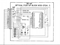
There are 3 pots on the laser sled - FO, FB and APC. I think it is this last one that controls power, but would appreciate a check on that if anyone knows better.
fran
There are 3 pots on the laser sled - FO, FB and APC. I think it is this last one that controls power, but would appreciate a check on that if anyone knows better.
fran
Hi. Power laser is APC. FB is F-E Balance, and FO is Focus Offset. Another thing, for to see RF signal in an oscilloscope, use probe attenuation x10. If you don't use a probe with attenuation, maybe the RF signal showed is low than real, and distorted. 750mVpp is low, you don't have nothing to lose. Move APC potentiometer and do the best you can.
Another tip, these 2k2 potentiometers varies its value throughout time, maybe the problem is not the laser, maybe is these tiny potentiometer. Best regard
Another tip, these 2k2 potentiometers varies its value throughout time, maybe the problem is not the laser, maybe is these tiny potentiometer. Best regard
I tried adjusting APC - but to no avail. I tried it both directions. When fully clockwise, I don't get disc spin up at the start - which matches the laser being completely off so that it doesn't read the reflective surface.
😕😕
😕😕
I agree it is not sounding good.
The other test you can do is to measure the DC voltage across that emitter resistor that connects to the PNP transistor. The current is then calculated using ohms law and compared to the value printed on the pickups serial number label. The last three digits correspond to the current so 12345596 would be 59.6 milliamps.
The current only flows when the laser lights and extreme care is needed when measuring. One slip of the probe and the laser would be destroyed. Safest way is to tag extremely fine leads across the resistor and connect those to the meter.
So o got looking at this more closely. I noticed a small electrolytic on the sled board. It had quite a high esr on my old meter. Not terrible, but not as low as it should be for that size (6 or 7r from memory, but on my meter even bigger caps measure less than 1r). Anyway I don't have a direct replacement. It's 33uf, and I only have 4.7uf in the same size. Is it worth swapping and seeing would that work?
Attachments
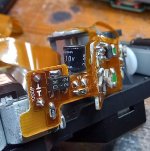
Hi. The resistor for to measure laser current is this smd resistor of 10 ohms, it's labeled 100. As you can see, the resistor is in the laser pickup, it is not easy to measure its voltage.
The capacitor should be replaced, but is not the main problem.
The capacitor should be replaced, but is not the main problem.
Ok, I will solder some fine wires to the resistor and measure voltage when it's reading.
Tomorrow.....
Tomorrow.....
Me back again.
So I soldered the extension wires across that 10R resistor. I measured 0.54v across it at spin up which is 54mA unless my maths is wrong. The serial number ends in 657 - so according to @mooly, the current should be 65.7mA.
Where do I go from here? The APC pot is just before its maximum (almost fully counter-clockwise).
fran
Interesting. It certainly sounds like the current is low and that would give low RF output. What is strange is that a failing laser should be running at ever higher current as the APC tries to maintain a failing light output.
As the current increase in the laser it first of all glows (like an LED) but it does not start start the lasing action until a certain threshold current is reached. Once that point is passed a very small increase in current causes a very large change in the laser light output.
It is impossible to guess what the problem is here. The photo diode could be faulty (it is on the same die as the laser chip) or there could be a problem with the control circuit itself. I've had the transistors fail on Philips players on more than one occasion but not on a Sony pickup.
"a very small increase in current causes a very large change in the laser light output."
Yes. I hope woodturner-fran get "the good point".
Yes. I hope woodturner-fran get "the good point".
This capacitor must be replaced due to its ESR being >10 ohms. Based on my experience, the uF value of the replacement capacitor can be either 33uF or 47uF. But 4.7uF would be too low. This capacitor functions as a low-pass filter for the APC feedback loop. When the capacitor ESR goes way up then the APC circuit will oscillate or become noisy, thus preventing the optical pickup from functioning.So o got looking at this more closely. I noticed a small electrolytic on the sled board. It had quite a high esr on my old meter. Not terrible, but not as low as it should be for that size (6 or 7r from memory, but on my meter even bigger caps measure less than 1r). Anyway I don't have a direct replacement. It's 33uf, and I only have 4.7uf in the same size. Is it worth swapping and seeing would that work?
Vintage Philips CD players which have CDM2 or CDM4 optical pickups have 33uF (or 47uF) APC capacitors which frequently fail with excessively high ESR. But these capacitors aren’t located on the optical pickup itself. Rather they are located on the main PC board (CDM4) or on the servo “sub PC board” underneath the transport. This make it easy to replace them because the size of the replacement capacitor doesn’t matter.
This suggests that the APC circuit is oscillating due to the dried out 33uF capacitor.Me back again.
So I soldered the extension wires across that 10R resistor. I measured 0.54v across it at spin up which is 54mA unless my maths is wrong. The serial number ends in 657 - so according to @mooly, the current should be 65.7mA.
Where do I go from here? The APC pot is just before its maximum (almost fully counter-clockwise).
fran
This capacitor serves as a low-pass filter for the APC feedback loop. When the capacitor ESR goes way up then the APC circuit will oscillate. This oscillation could be the reason why you cannot raise the laser current above 54mA.
You might want to go ahead and try the 4.7uF capacitor which you already have. In my opinion the ESR is more important than the uF. So the 4.7uF capacitor may work OK. However it would be best to eventually get a 33uF or 47uF capacitor of the correct physical size.
I recommend rotating the APC trimpot back to midrange before applying power. Otherwise there might be too much laser current after replacing the capacitor.
With a good capacitor installed then you should be able to adjust the laser diode current to within 10% of the original factory value without needing to rotate the APC trimpot all the way to the end.
-EB
- Home
- Source & Line
- Digital Source
- Help Sony X779ES not reading TOC/KSS272A