I came across this Dynaco kit company, in the photo you'll see wire coiled around the capacitors, what the heck is this all about?
Amplifiers
– Tagged "Amplifier"– Page 2
– Funtastic Vintronics
Amplifiers
– Tagged "Amplifier"– Page 2
– Funtastic Vintronics
I came across this Dynaco kit company, in the photo you'll see wire coiled around
the capacitors, what the heck is this all about?
The series output inductor, found in many ss amplifiers, isolates load capacitance from the amplifier,
and so enhances stability.
Usually the output inductor is wound around a 10 ohm power resistor rather than an electrolytic capacitor,
but the early Dynaco designs were single supply circuits with an output DC blocking capacitor, so that was
used instead.
Last edited:
Philco 'Trick' Capacitor & Others
Many of us Olde Buzzards like wiseoldtech & others may have stripped discarded receiver chassis to recover usable parts. So here is a capacitor some may have seen & wondered what purpose it filled. You can find a complete description at-
https://www.philcorepairbench.com/i-f-wave-trap-and-special-capacitor/
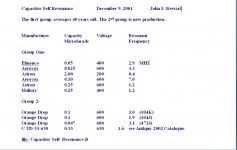
About 20 yrs ago I measured the series resonant frequency of several common capacitors, see attached.
I'm not much of a fan of the Zobel Network on common toob amps, the leakage reactance of the OPT is still in series with the signal. But for many SS Amps it does help.🙂
Many of us Olde Buzzards like wiseoldtech & others may have stripped discarded receiver chassis to recover usable parts. So here is a capacitor some may have seen & wondered what purpose it filled. You can find a complete description at-
https://www.philcorepairbench.com/i-f-wave-trap-and-special-capacitor/
About 20 yrs ago I measured the series resonant frequency of several common capacitors, see attached.
I'm not much of a fan of the Zobel Network on common toob amps, the leakage reactance of the OPT is still in series with the signal. But for many SS Amps it does help.🙂
Attachments

FWIW, winding an inductor around an aluminum can gives you an inductor with incredibly poor properties. Probably good enough to improve stability but not great practice.
Many of us Olde Buzzards like wiseoldtech & others may have stripped discarded receiver chassis to recover usable parts. So here is a capacitor some may have seen & wondered what purpose it filled. You can find a complete description at-
https://www.philcorepairbench.com/i-f-wave-trap-and-special-capacitor/
About 20 yrs ago I measured the series resonant frequency of several common capacitors, see attached.
I'm not much of a fan of the Zobel Network on common toob amps, the leakage reactance of the OPT is still in series with the signal. But for many SS Amps it does help.🙂
Yes sir.
I've done restorations on those old Philco radios with the caps being wrapped like that.
About 20 yrs ago I measured the series resonant frequency of several common capacitors, see attached.
For a LS cross over filter I once connected several 0,5-10uF caps to a 'wobbulator' tone generator and observed the frequency when the capacitor started producing sound. It's an EL84 based unit so 5W out max, I estimate its output impedance 10 ohms max. My findings were quite lower, in the few kiloHertz range. Those were the days I was concerned the caps would interfere with musical reproduction 🙂
The quietest units were those modern film types which I used lots of in parallel.
The problem with a coil wound on a conducting cylinder of Al is that the magnetic field is excluded from inside the capacitor case, so the inductance is way less than its dimensions might suggest.
And there will be eddy-current losses in the caps too.
And there will be eddy-current losses in the caps too.
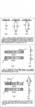
There is a different kind of capacitor described in the link to the Philco App Note. That would be Figure 3 in my first post. It forms a trap at 455 KHz by making a connexion to a point on the cap outside foil so that that forms part of the required inductance. An interesting read for the curious. And the math to support it.
https://www.philcorepairbench.com/i-f-wave-trap-and-special-capacitor/
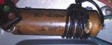
And another wire wrapped example attached.🙂
https://www.philcorepairbench.com/i-f-wave-trap-and-special-capacitor/
And another wire wrapped example attached.🙂
Attachments
The problem with a coil wound on a conducting cylinder of Al is that the magnetic field is excluded from inside the capacitor case, so the inductance is way less than its dimensions might suggest.
And there will be eddy-current losses in the caps too.
All that might be true of course, but the Philco radio mentioned is a small table top AM/BC model from the 1940's, so surely nothing critical about the coil inductance.
To save on coil forms?
And since Aluminum is hard to magnetize, it would work like an air inductor?
And same connection points, so some labor saving for the inductor and capacitor network?
Those old caps were wax dielectric, pretty durable.
And since Aluminum is hard to magnetize, it would work like an air inductor?
And same connection points, so some labor saving for the inductor and capacitor network?
Those old caps were wax dielectric, pretty durable.
Guys, look at the pictures. Not a zobel. The wire appears to be the connection between the two negative sides of two large filter capacitors. Like a CLC filter. But...
As was stated, it would have very low inductance since there is a solid aluminum cylinder inside the coil.
It's nonsense. But it looks cool, and I'm sure there is some reason that us engineers would not believe.
Pete
As was stated, it would have very low inductance since there is a solid aluminum cylinder inside the coil.
It's nonsense. But it looks cool, and I'm sure there is some reason that us engineers would not believe.
Pete
- Home
- Amplifiers
- Tubes / Valves
- Why is there wire coiled around these capacitors?