I have designed a boostered opamp audio amplifier based on AD820 and TIP125, TIP120.

The output stage is controlled by the currents through the Vcc and Vee power rails by use of the resistors R4 and R5. The bias current through the output transistors is set by an adjustable current source LM334 and the fine trimmer R8 (10 Ohm). The output stage is in common emitter configuration. In this way the amplifier can operate with rail-to-rail output voltage swing.

What do you think about this circuit?
An externally hosted image should be here but it was not working when we last tested it.
The output stage is controlled by the currents through the Vcc and Vee power rails by use of the resistors R4 and R5. The bias current through the output transistors is set by an adjustable current source LM334 and the fine trimmer R8 (10 Ohm). The output stage is in common emitter configuration. In this way the amplifier can operate with rail-to-rail output voltage swing.
An externally hosted image should be here but it was not working when we last tested it.
What do you think about this circuit?
Last edited:
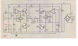
The circuit is suitable for amplifier B (without bias). Thermal stabilization can be added like TO-126 diodes in the power supply arms of the IC. Search the net Stonecold (Elektor №8 и 21) G.Schmidt, Germany. Усилитель мощности STONECOLD. Принципиальная схема, описание, чертеж платы.
Last edited:
An externally hosted image should be here but it was not working when we last tested it.
Schmidt G. Current dumping amplifier - Elector. 1978, .№ 7/8.
Last edited:
An externally hosted image should be here but it was not working when we last tested it.
Current Dumping Amp
Versatile bridge mode op amp circuit
This circuit works different in the classical emitter follower configuration. In this configuration you cannot get an output voltage that is close to the power rails. You will at least get a voltage drop which is equalt to the base emitter voltage of the output transistor or two times the base emitter voltage for darlington transistors.
Last edited:
In the current dumping amp you will meet issues with crossover distortion, because in a certain low signal range both output transistors are off until they carry carry the current required by the load.
In my design there is no connection between the output of the opamp and the output of the amplifier. So both transistors of the output stage are permanently on and carry at least the quiescent current of the output stage.

You can see it in the figure above in the curves of the transistor currents and in the curves of the transistor power dissipation.
- Home
- Amplifiers
- Solid State
- boostered opamp audio amplifier