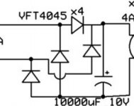
I am working on an amp and I need to supply 3A at 6.3VDC to a 3C24 tube.
I am working from this schematic but I can't really figure out how to physically mount the diodes so they are easily wired up AND heatsink them appropriately.
I'd ideally like to use the chassis as a heatsink but I'm totally open to suggestions.
Any pictures of similar set-ups would be greatly appreciated!
Attachments
How about creating a bridge rectifier circuit board to hold them, perhaps like this one? The diodes are bolted to the chassis, which acts as a heatsink. In this case, it's the front panel where the blue LEDs are located.
Click on the picture to see it full size and undistorted.
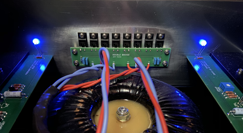
You can also see a C+RC "transformer secondary snubber" in the bottom corner of the board.
I found that photo attached to post #119 of this thread
Click on the picture to see it full size and undistorted.
You can also see a C+RC "transformer secondary snubber" in the bottom corner of the board.
I found that photo attached to post #119 of this thread
If you think the diodes need heatsinking (it depends on their rating) then get yourself a BRIDGE RECTIFIER. This is a device with four connections, the larger ones have a hole for chassis mounting. Search the internet for images. AC in, and DC out.
You could use a chassis mounted bridge rectifier such as the KBPC2510. It's rated for 25 A. Then solder the capacitor directly to the bridge and bolt the bridge to the chassis.
Tom
Tom
Sounds great but I am concerned about replacing the VFT4045 rectifiers specified with something else. I'm just not smart enough to swap parts like that.
There no google data for VFT4045 2 pin. Data sheets on 3 pins with B & C prefix.
MOS type means <0.3V voltage drop at 5A. How high is the voltage feeding this rectifier circuit?
MOS type means <0.3V voltage drop at 5A. How high is the voltage feeding this rectifier circuit?
An externally hosted image should be here but it was not working when we last tested it.
Exactly what I would do too Tom. Plenty of current headroom and not worry about overloading.You could use a chassis mounted bridge rectifier such as the KBPC2510. It's rated for 25 A. Then solder the capacitor directly to the bridge and bolt the bridge to the chassis.
Tom
I would like to use a premade bridge. The tube in question, the 3C24, draws 3A @6.3V and is a DHT.
The designer is using the 6.3V 5A winding on the existing transformer.
The designer is using the 6.3V 5A winding on the existing transformer.
Boards arrived without problems. Thanks for the files and the other help!
Are the CRC snubber values standard? Any ideas what to use?
Are the CRC snubber values standard? Any ideas what to use?
If you're using a PCB designed by Jeff Young, he's a big proponent of in-vitro snubber tuning. He created this Forum thread which may be useful. Don't get off on the wrong foot by posting a question to his thread "results ONLY", you don't want to annoy him unnecessarily.
_
_
I'm digging that but I'm not sure I am up to creating my own circuit boards yet.
Great find!
The first pcb design is usually the hardest going through the design loop.
For such a simple circuit you could just create a pcb without a schematic.
Loads of free pcbcad packages around now.
- Home
- Design & Build
- Construction Tips
- How to Construct this Circuit?