I am trying to use a old power transformer to breadboard some valve audio projects but the heater winding is give me too much voltage!
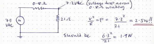
The calculations below don’t include the reactance of the winding at 50Hz, so it’s in the DC limit. But they indicate that I’m will likely dissipate way to much power in the heater filaments if I connect a valve (ECC83 triode).
Unloaded, I get 7.5VAC. So with a load, I will get 7.2V. Which means the filament will dissipate 2.5W rather than 1.9W.
Hopefully my calculations are off because at 50Hz the voltage will be reduced further by the reactance of the windings. But I’m unsure and don’t want to kill my tubes! Help!
Do I need a new power transformer? What would you do?
Attachments
Just use a series resistor to drop the excess voltage.
For example, to drop an extra 1V, with a filament load of 300mA,
use 1V/0.3A = 3.3R in series, with a power rating of 1V x 0.3A = 0.3W.
For example, to drop an extra 1V, with a filament load of 300mA,
use 1V/0.3A = 3.3R in series, with a power rating of 1V x 0.3A = 0.3W.
Last edited:
I once accidentally applied 25VDC to a valve heater and got away with it so I would have though 7.5VAC would be ok.
Unless transformer is only 2 watts.
Unless transformer is only 2 watts.
I am trying to use a old power transformer to breadboard some valve audio projects but the heater winding is give me too much voltage!
The calculations below don’t include the reactance of the winding at 50Hz, so it’s in the DC limit. But they indicate that I’m will likely dissipate way to much power in the heater filaments if I connect a valve (ECC83 triode).
Unloaded, I get 7.5VAC. So with a load, I will get 7.2V. Which means the filament will dissipate 2.5W rather than 1.9W.
Hopefully my calculations are off because at 50Hz the voltage will be reduced further by the reactance of the windings. But I’m unsure and don’t want to kill my tubes! Help!
Do I need a new power transformer? What would you do?
If you're using the whole transformer, including HV secondaries, the voltage on the filament taps will drop further as the whole secondary experiences current demands. But even under full load I'd expect you'll still get 6.9 or something like that.
7.5VAC unloaded would not be at all unusual for an old power tranny with 115 or 117V primaries. Unless you use a variac or a bucking transformer on the primary, you're *always* going to get overvoltage, especially on the filament taps. Even a relatively new Hammond will do this.
Since you're breadboarding, I suggest you either use a variac, a bucking transformer, or more simply and cheaply, purchase a large adjustable resistor, say 2 ohms at 10 watts, put it series with one leg of the filament tap, and adjust as needed.
I keep a fairly large supply of 5W cement resistors, ranging from .1 to 2 ohms, for just this sort of thing. When restoring an older amp or using older power transformers, it's almost inevitable that the filament supply will need some downward adjustment.
A pair of diodes in anti parallel will drop about 0.7V depending on the diodes... Easy way to drop voltage.
Thanks all! That a great idea to keep around those dropping resistors. Yeah I need to order in some parts if I want to continue down this route. But part of me things it should either order a modern power transformer or just use a regulated supply!
Oh! Diodes to rescue! Didn’t think about that.
Thinking about that a bit more... will that change the voltage requirement because in addition to dropping 0.6-0.7V it will also rectify, so to supply correct time average I'm going to need to supply more voltage. Unless I just do DC heaters, but that seems a bit overkill, was hoping the throw something together.
Thinking about that a bit more... will that change the voltage requirement because in addition to dropping 0.6-0.7V it will also rectify, so to supply correct time average I'm going to need to supply more voltage. Unless I just do DC heaters, but that seems a bit overkill, was hoping the throw something together.
Last edited by a moderator:
Yes, a single diode will give an average voltage of half that of a full wave rectifier,
because the output is zero half the time. Use a full wave bridge rectifier instead,
with a 2200uF or larger capacitor. Then you will have to use an RC filter with around
3.3R (adjust to make 6.3VDC) and 2200uF, to both drop the excess voltage,
and reduce the 100/120Hz ripple.
A single series resistor, supplying a reduce AC voltage, is much simpler.
Last edited:
He probably needs more voltage drop, so maybe two or three diodes in series, and with
two or three more diodes in antiparallel. But this might introduce noise in some circuits.
For testing purposes, I would just use a Variac to adjust the filament AC voltage.
two or three more diodes in antiparallel. But this might introduce noise in some circuits.
For testing purposes, I would just use a Variac to adjust the filament AC voltage.
Last edited:
Oh I understand better now. So two diodes in parallel but reversed direction. So there is voltage drop and no rectification. Spot on.
Just to warp things up.
I tested out a pair of diodes in anti-parallel which should drop 0.57V. When I measured this with mains voltage (around 240V @ 50Hz) a single pair dropped the voltage on the secondary to exactly 6.3V! I think the reactance of the winding at 50Hz contributed some additional drop.
So if someone else is reading this in the future, do calculations in DC to make an estimate of the drop required, and then try it out first; you might need less drop than you calculate, once AC is applied.
Last edited by a moderator:
A diode junction that drops 0.6V at 1 Amp generates 0.6 Watts heat.
A 0.6 Ohm resistor that drops 0.6V at 1 Amp generates an identical 0.6 Watts heat.
Take your pick 0.6 Watts heat, or 0.6 Watts heat.
Take your pick, Noisy voltage drop, or No-noise voltage drop.
It is not quite that simple, but hopefully you get the idea.
A 0.6 Ohm resistor that drops 0.6V at 1 Amp generates an identical 0.6 Watts heat.
Take your pick 0.6 Watts heat, or 0.6 Watts heat.
Take your pick, Noisy voltage drop, or No-noise voltage drop.
It is not quite that simple, but hopefully you get the idea.
Oh that’s an interesting point, what’s the noise characteristics like between resistors and diodes?
I know the thermal noise is proportional to the root of the resistance, so that huge resistance of the non conducting diode will be larger than for a resistor and contribute more noise. I have no ideas about the Excess noise (microvolts per volt) of diodes; could not find in the database either.
But, yeah, I just had a couple of 1N4007 lying around.
Thanks for all your helpful folks.
Diodes will generate new switching voltages (di/dt) that most folk are trying to avoid, and couple it to other windings. Also, the waveform is no longer a sinusoid, so conventional meters will read RMS incorrectly, and heating will be different than a sinusoid.
All good fortune,
Chris
All good fortune,
Chris
Last edited:
That makes perfect sense, the threshold voltage will introduce flat regions when the AC voltage approaches nodes in the cycle, which in the frequency-domain are high frequencies.
The effect can be seen here, https://tinyurl.com/yj4xm5aw
Thanks for explaining.
The effect can be seen here, https://tinyurl.com/yj4xm5aw
Thanks for explaining.
- Home
- Amplifiers
- Tubes / Valves
- Heater windings are giving me too much voltage!