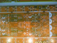
Hi. For sale high quality (2mm PCB), exact clone pcb of the original Accuphase A-65 class-A Mosfet amplifier. The PCB are so exact that you can use directly the orginal Accuphase A-65 Service manual. I also made a detailled BOM to match these these pcb with current parts.
The main amp PCB can also be modified rather easily (not a beginner job), to be rather a P-7100 transistor final stage (adding some transistors, cutting and routing some traces, etc) The main power Mosfet or Transistor have the same pinout, so you can solder either of them.
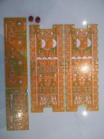
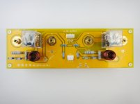
The kit includes the two amplifier PCB, Output speaker connector & speaker relay PCB, custom Zobel inductors, Input & Front-end PCB, detailed BOM and the original A-65 service manual (pdf). Not shown on the picture, I'll also include the rotary selector switch that goes on the input PCB, no extra charge...
What is missing are the main amp pcb bus bar, but that can be easily replaced by short section of good quality wires. It will probably be better sounding anyway than the crapy original bus bar. If interested I can add at no cost a good lenght of large gauge enameled solid core wire for this.
As reference only I also posted some pictures of the original assembled pcb...
To complete the amp you just need a soft-start and DC protection circuits. Naturally if you want front meters as the original, you'll also need meter driver pcb, but this is optional.
I paid 200U$ for the kit + extra shipping.
Letting it go for 100U$ + shipping + Paypal fee. My loss, your gain...
Thanks for looking
SB
The main amp PCB can also be modified rather easily (not a beginner job), to be rather a P-7100 transistor final stage (adding some transistors, cutting and routing some traces, etc) The main power Mosfet or Transistor have the same pinout, so you can solder either of them.
The kit includes the two amplifier PCB, Output speaker connector & speaker relay PCB, custom Zobel inductors, Input & Front-end PCB, detailed BOM and the original A-65 service manual (pdf). Not shown on the picture, I'll also include the rotary selector switch that goes on the input PCB, no extra charge...
What is missing are the main amp pcb bus bar, but that can be easily replaced by short section of good quality wires. It will probably be better sounding anyway than the crapy original bus bar. If interested I can add at no cost a good lenght of large gauge enameled solid core wire for this.
As reference only I also posted some pictures of the original assembled pcb...
To complete the amp you just need a soft-start and DC protection circuits. Naturally if you want front meters as the original, you'll also need meter driver pcb, but this is optional.
I paid 200U$ for the kit + extra shipping.
Letting it go for 100U$ + shipping + Paypal fee. My loss, your gain...
Thanks for looking
SB
Attachments


Last edited:

Too ban not the original P-7100 version, I would take of your hand gladly. I am just looking for that at the moment. Since a do not have the two schematic to see the required modification, how difficult, cutting, jumping etc. I can not buy it like that.
I have both schematics, and can send you the info, already did the research to know how to modify it…
SB
SB
Sylvain is great guy, if nobody will buy, i will buy it when I have time to play. have 50psc matched toshiba bipolars if anyone willd decide to play earlier than me 🙂
BJT VS FET power stage I think it should have minimum an extra driver stage difference between the two which not so easy to be modified. Possible, yes but I do not like to start a project like that. I will wait to find the P-7100. I have some Toshiba mosfets but not that many and not well matched.
P-7100 mods was just a suggestion, you can build the real A-65 mosfet, class-a amp with this set…
I am only interested on P-7100. Easy to guess why...
Someone who owns the mosfets sure it worth to build. Not to me..
Someone who owns the mosfets sure it worth to build. Not to me..