With the knowledge of having built a few existing proven passive designs and making plenty of my own designs with active DSP crossovers, I decided to give a 2 way passive XO a crack. With the success I've had with augerpros waveguide I mated the Sb26ADC up to the MW19P-4 and here's what I came up with. Looking for any critiques, errors, am I going to eventually blow an amp up. So far its working and sounds pretty good but it would be good to know what to improve if I can. Its worth noting I jimmied the XO up from parts I already had lying around so some compromises were made. Also I didn't nearfield stitch the LF response on the VCAD Measured set but have attached a REW measurement where I did.
Simulated:


Measured:


Any comments most appreciated. Its been quite the learning curve.
Simulated:
Measured:
Any comments most appreciated. Its been quite the learning curve.
That stuff is all Greek to me, but it looks pretty sweet. Why would something like that kill an amp, is it an impedance thing?
If your transducer datasheets have resistance+inductance models, then you could put the whole crossover+speaker into a simulator. Then plot current versus frequency. You are allowed about 3 amps per TO3 transistor pair, 2.5 for TO264 TO3P etc. 4 amps peak. More than that the circuit blows up the amp. Actual power rating of the amp may be less due to heat sink limitations etc. P=(I^2))*Z
If the transducers don't have data, then you could make an approximation with a DVM for resistance and and inductance meter. Or for inductance exercise the transducer at various frequencies and measure the AC current, then approximate reactance with sqrt(R^2+(2*pi*f*L)^2).
Without a simulator you can reduce the circuit to a vector reactance using kirchoff's laws. Then use a calculator to predict current.
Last edited:
The DI peak near 2k is lower in the measured version. Is that because you simmed driver separation but didn't measure vertical after crossing?
Bingo AllenB - measuring floor-standers vertical is laborious. I hope to find some time to do that soon.
Funny thing is the in-room measurements show a 2k Xover dip. I suspect I haven't got the XO quite right.
Funny thing is the in-room measurements show a 2k Xover dip. I suspect I haven't got the XO quite right.
Slightly off-topic - but I am interested in where you printed your waveguides here or overseas? (or did you self print)? Do you have any photos of waveguide mounting?
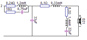
What does the RLC network on the tweeter do? is it causing the dip in your high treble impedance?
Edit - do you think you could get away with a lower XO point with the MW19? There's some odd order HD peaking around 2KHz depending on voltage level:
Satori MW19P-4 | HiFiCompass
I don't know at what point the sb26adc would sound unnatural - stress. I believe it has decent xmax (0.5mm?) so may not be excursion limited esp. with WG loaded at a 1500Hz XO.
Last edited:
Seems to me the BSC cuts away too much at 400-500Hz. Otherwise a nice job! I'd like to see the pictures.
Looks like I've still got a bit of work to do. Thankfully the crossovers only cable tied to timber and connected with wago connectors at this stage so changes easily made. I'm franticly reading through Vance Dickinsons Loudspeaker Cookbook to keep my mind up with my tools at the moment.
Pida, thats extremely helpful. Thank you.
Allen, thanks, will try experiment with phase.
Markbakk - agreed, this is audible too IMO. Main inductor perhaps a bit large.
Dave - had to use xometry. They are very good prints. Tried to go local but no luck. Photos here of cabinet for you. Yes the LCR is sort of providing a low Q dip (i believe a 'notch' filter?) between 5-10k bringing down the excess tweeter energy there. May not be required depending on XO slopes.

I think I have a standing wave around 180hz. Its visible from in the nearfield splicing and in the port measurement that is likely a byproduct of the tall and slim cabinet. Hope to fix with stuffing or baffles. My tuning ended up much lower than simulated too, around 33hz compared to 37hz so back to the drawing board there perhaps, maybe a cabinet rethink. 28L is the final volume currently. The goal is a nice slim veneered 2-way floorstander for the lounge.


Pida, thats extremely helpful. Thank you.
Allen, thanks, will try experiment with phase.
Markbakk - agreed, this is audible too IMO. Main inductor perhaps a bit large.
Dave - had to use xometry. They are very good prints. Tried to go local but no luck. Photos here of cabinet for you. Yes the LCR is sort of providing a low Q dip (i believe a 'notch' filter?) between 5-10k bringing down the excess tweeter energy there. May not be required depending on XO slopes.
I think I have a standing wave around 180hz. Its visible from in the nearfield splicing and in the port measurement that is likely a byproduct of the tall and slim cabinet. Hope to fix with stuffing or baffles. My tuning ended up much lower than simulated too, around 33hz compared to 37hz so back to the drawing board there perhaps, maybe a cabinet rethink. 28L is the final volume currently. The goal is a nice slim veneered 2-way floorstander for the lounge.

A standing wave at 180, you say. Without giving it much thought it also looks like you have a cancellation at (180x2) and another peak at (180x3). Maybe you could try to prevent these higher frequencies from reaching the port.
Where the port is at? Put it on the back panel to reduce mid leakage audibility somewhat and middle height to reduce coupling of the lowest mode (180Hz) into the port. There should be velocity node (of the lowest mode) at middle of the height and my hunch is that it leaks less through the port than a pressure node would. Optionally you could try the port for example at 1/3 height to avoid second lowest mode pressure node which is at the middle. Using the same logic worst position for a port would be end of the longest dimension where every mode, that are not affected too much by the stuffing, has a pressure node. Anyway, time for little experiment to find a spot for the port that doesn't have too many issues 😉 Other option would be to put the driver at middle of the height, not possible here. Stuffing could help some especially above the lowest mode, but internal baffles only make modes lower in frequency if any (even longer path length). I'd say try to tame the lowest mode with the port position and stuffing for the rest. Have fun!🙂
Last edited:
Some bonded acetate fibre in an old pantyhose attached to the cabinet just under the woofer could do the job of destroying the standing wave and weakening the mid frequencies engaging the port resonance. And it won't compromise the reflex tuning too much.
mainframe: I also suggest to add RLC in parallel to tweeter to compensate that Fs peak. I think phase tracking will improve as well.
Anyway, I think your latest sims look quite good and it is time to do actual measurements. Further simulations will not bring you better results, so it is worth spending time with measuring.
Anyway, I think your latest sims look quite good and it is time to do actual measurements. Further simulations will not bring you better results, so it is worth spending time with measuring.
You might have already addressed this with Pida's suggestion. But Troel's highlights a potential problem with the "large inductor to do baffle step" approach here:
SEAS CURV
Read the Crossover section. I can see a similar 400Hz dip as per your original crossover not apparent on the inbox raw woofer response.
PS: thanks for the details on the waveguide printing source. I presume you used the waveguide file "as is " without any need to scale / size? Did you need to set any in-fill parameter/percentage? (if so what did you specify?) sorry for all the questions - trying to avoid newbie errors when making a request.
- Home
- Loudspeakers
- Multi-Way
- First Passive 2 way design - incl. Augerpro Waveguide