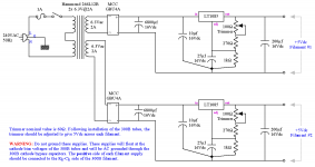
I'm working out details on a 300B build and am leaning towards using LT1085 regulators for the DC heaters based off this schematic.
My question: will mounting these regulators to the underside of a steel chassis with thermal paste/insulator kit be enough to keep them alive, or are they going to need a dedicated heat sink?
If they need a dedicated heat sink, I'll probably mount them above the top plate to keep their heat away from the caps etc. inside the amp, so would like to plan for that, if simply sinking them to the chassis isn't enough.
I'm sure a debate over A/C vs D/C heaters will erupt, which is fine once I get an answer for my heat sink question 😉
Attachments
Might be ok, but the tubes will also be relentlessly heating up that same aluminum chassis. If you ventilate the chassis, a clip on sink might be good, I'd go to the LT1083 instead which is for 7.5A, the 300B draws 1.2A, LT1085 is for 3A but I tend to overdo things. Maybe some venting holes right above the clip on heatsinks, holes on the bottom to get some convection going. For DHT's there is seldom a dispute over AC vs DC here, DC predominates.
Last edited:
My question: will mounting these regulators to the underside of a steel chassis with thermal paste/insulator kit be enough to keep them alive
My friend use one of my 300B working such way more than a decade.
Please calculate regulator dissipation / (Vin-Vout)*I /, and hold it near to the minimum, (6.5V-5V)*1.25A.
I use DC heating for my 300bs. Like many others I use Rod Coleman regulators - much better sound than LT1085 which they replaced. See Lyrima, UK. A heatsink will get hot. Mine are on my top plate which is 4mm aluminium, so that is a fair heatsink anyway. Size is about 5x5x3cm heat sink per regulator.
I did it a different way. I used a 100VA 12+12v transformer to give headroom for the Rod Coleman regulators. A 50VA 12+12 got hotter than I wanted. A 50VA 9+9v transformer might have been OK but I had the 100VA 12+12v in stock. The heating current is continuous, of course, and this does generate heat.
This would all be much larger than the size you planned for, and hopefully your calculations will work off a 6.3v supply. It's possible to use an external box for the heater supply with an XLR 4-pole connector. I do that when I put chokes in the filament supply for extra smoothing. If you want something smaller, you could go AC with a hum pot if the DC doesn't work out.
.
Last edited:
The 1085 is likely good for about 5W when mounted to the chassis (insulated, of course). With 1.2A each, they could take a voltage drop of 4V or so. Since they have a 1V dropout, there would plenty plenty of headroom. If there's more than 4V (unlikely with that circuit) a series or shunt resistor could take some heat elsewhere. More likely is voltage too low... if ripple troughs drop below 6V, it'll drop out of regulation and pass ripple through. In that case, change rectifiers to Schottky, increase filter cap (best to use multiple in parallel for ripple current, low ESR)
Perhaps you should go for a L200 set at a maximum current of 1.8A to provide soft start for the tube. This IC is also a lot more stable than a LT1085.
Cheaper alternative to LT1085 is LD1085.
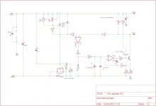
Attached you will find the schematic of the regulator i designed for these kinds of tubes.
Cheaper alternative to LT1085 is LD1085.
Attached you will find the schematic of the regulator i designed for these kinds of tubes.
Attachments
Last edited:
Put a big wirewound power resistor across the regulator. Size it to provide two thirds of the current required to run the filament.
The regulator will provide the start up current and then loaf. However it will regulate the voltage all the time!
The regulator will provide the start up current and then loaf. However it will regulate the voltage all the time!
I use the chassis as a heat sink, but use only aluminum chassis - not steel chassis. I believe steel should work OK. Been doing rhis for about 30 years now, and no problems.
I use LT1085 as pre-regulators which an output set to 8.5V - 9V into Coleman regulators. (Currently 8 of them in my system) They are not expensive.
I use LT1085 as pre-regulators which an output set to 8.5V - 9V into Coleman regulators. (Currently 8 of them in my system) They are not expensive.
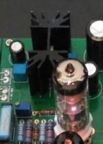
I also use LT1085 for my dac tube output, the key is to use trafo AC output closer to desired DC output. LT chip has low voltage drop so AC to DC conversion 1.3x-1.4x output can be considered as voltage drop calculation range
example : for my 6.5V heater requirement, I use 9Vac trafo output (use 6Vac-7Vac) should be fine but 9Vac is that i have. previously i use 15Vac, eventhough i use 2 stacked heatsink, it's very hottt. now with 1 heatsink it still fine
maybe you can test it using regular heatsink vs bolted to chassis and monitor the temperature
Attachments

You're looking at 2-2.5 W dissipated per regulator. I'd use a small board-mounted heat sink as those shown in Post 10.
Steel isn't fantastic as a heat sink.
It may be that the regulator would survive on the steel heat sink, but you'll get better reliability if it runs cooler.
Tom
Steel isn't fantastic as a heat sink.
It may be that the regulator would survive on the steel heat sink, but you'll get better reliability if it runs cooler.
Tom
I think I'm going to sandwich a aluminum heatsink between the regular and the steel chassis. Thanks for the advice 🙂
I think I'm going to sandwich a aluminum heatsink between the regular and the steel chassis. Thanks for the advice 🙂
That's what I did and it worked great. Plus the dual regulator I used is being pushed to its limit and runs pretty cool now.
- Home
- Amplifiers
- Tubes / Valves
- Heat sinking 300B LT1085 heater regulators