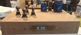
I just completed design and assembly of a DAC based on the Soekris dam1021 R-R2 resistor ladder DAC with a 6SN7 tube buffer stage. This is my first DIY project.
Components
Project goals
Implementation
Lessons learned
Evaluation
I really enjoyed an AudioLogic triode tube DAC that I owned for the past 25 years. When the AudioLogic DAC failed and couldn’t be repaired, I decided I would try and build my own.
I am really enjoying the nuance and detail of the Soekris DAC.
I am also impressed by how closely the actual circuitry matched the spice model predictions.
This has been an enjoyable project. I've benefitted greatly from the knowledge available here and elsewhere on the internet.
Next steps
Components
- Soekris dam1021 R-2R DAC
- DIYINHK x USB to I2S interface board
- Arduino microcontroller
- 16 character vacuum fluorescent display
- Lundahl 1949 line input transformers
- Lundahl 1930 parafed line output transformers
- Lundahl 1667 anode chokes
- Edcor 300-0-300 mains transformer
- Edcor 5H power supply choke
- Audiophonics R-Core transformer for low voltage digital power supplies: 12-0-12 V and 9 V
- 6SN7 triode tubes
- 5U4GB rectifier tube
Project goals
- R-2R ladder DAC
- Tube based high voltage power supply
- Tube based buffer stage
- Separate linear, regulated power supplies for the digital electronics
- Linear regulated DC filament supply
- Front panel source selection: USB, SPDIF1, SPDIF2
- Display operating mode, bit rate, and lock status on the VFD display
- Eliminate audible pops by opening/closing the analog connections and switching sources using relays and logic implemented on the Arduino
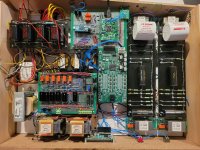
Implementation
- The analog section consists of a parallel connected 6SN7 cathode follower feeding a parallel connected 6SN7 parafed gain stage
- Lundahl line input and output transformers
- Turret boards used for the high voltage power supply and buffer circuitry
- Perforated prototype boards (Bud Industries) for the power supply and logic boards
- I used optical isolator chips to isolate the DIYINHK USB interface board, source select switch, DAC lock, and DAC source select pins from the Arduino
- I used PSU Designer II software to develop and model the power supplies
- I used LT Spice to develop and model the vacuum tube electronics
- I've always liked the look of VFD displays. I think it's a shame they are being phased out.
Lessons learned
- I created a Visio stencil to represent the holes on the prototype boards. I found Visio to be a useful tool to lay out the component placement and wiring of the prototype boards. However, making board changes in Visio proved tedious. I wish I could have found dedicated software for laying out prototype boards. I didn’t want to go through the process of having circuit boards fabricated for a one off design.
- I am also using Visio to design the chassis. The dimensioning feature gives me the X/Y offsets that I need for placing the fasteners in Protocase Designer.
- I found .296 inch Mill-Max pins (DigiKey part number ED10464-ND) really useful for routing wires around corners and for bringing wires from one side of a prototype board to another. These pins allowed me to easily create two layer boards.
- I bought a used HP signal generator on EBay and a LOTO instruments OSCA02L USB oscilloscope from Amazon for circuit testing, which proved very useful. I’m happy with the USB oscilloscope and it seems adequate for use by a hobbyist.
Evaluation
I really enjoyed an AudioLogic triode tube DAC that I owned for the past 25 years. When the AudioLogic DAC failed and couldn’t be repaired, I decided I would try and build my own.
I am really enjoying the nuance and detail of the Soekris DAC.
I am also impressed by how closely the actual circuitry matched the spice model predictions.
This has been an enjoyable project. I've benefitted greatly from the knowledge available here and elsewhere on the internet.
Next steps
- I’m currently designing a five sided steel enclosure using Protocase Designer and will send the completed CAD file to Protocase for fabrication
- I’m using concealed head self-clinching fasteners so there won’t be any visible fasteners on the steel chassis
- I'll clean up the wiring when I move everything to a permanent chassis. I didn't want to cut the leads from the transformers and chokes until then.
Attachments
You have clearly had fun but the topology baffles me. Why an input transformer? Why a follower at input and a gain stage at output? How much gain do you need anyway?
You may like calling this a tube dac, but it makes more sense to think of it as a tube preamp sharing a housing with a dac 🙂
You may like calling this a tube dac, but it makes more sense to think of it as a tube preamp sharing a housing with a dac 🙂