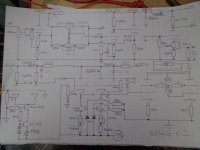
I'm building a class AB2 amp and I have an issue with LF stability. It uses a couple of 6164's in PP AB2, see provisional schematic. Not shown is the PSU. Which consists of an IE core tfmr with a Rpri of 7.5r, and an Rsec of 32r. Vsec is 325v AC RMS into a fuse then a bridge rectifier the into a CLC filter of two 700u caps in series (350u) then a 5H choke, the two more 700u caps in series. All caps have 180k series resistors across them. HT is 410 Load is 2562r as far as I can make out (410v HT/0.160mA) The Idc of 0.160mA is quiescent, I'd expect it to be about 1.5 times that at full whack.I tried adding some small caps in parallel with the 2nd cap, a 10u and a 1u but no improvement. I worked out Xc and XL which is Xc = 454r and Xl = 3140 at 100hz and the PSU source resistance as 45r, but after that am not sure where to go next.
I've looked at all my references and cannot find how to calculate whether a power supply is potentially resonant at LF or how to design for stability or how to fix potential LF instability. I've looked in Radio Designers, Morgan Jones Valve amps, Crowhurst and loads more reference books as well as online.
I tried adding some small caps in parallel with the 2nd cap, a 10u and a 1u but no improvement. I worked out Xc and XL - which is Xc = 454r and Xl = 3140 at 100hz and the PSU source resistance as 45r, but after that am not sure where to go next.
Any ideas welcome. Andy.
Attachments
Last edited:
The choke will resonante with the following capacitance at
f = 1/ (2 pi sqrt[LC])
This is about 3.8Hz in your circuit.
Resonance can be completely damped with a resistance in series with the choke, equal to:
R = 2 sqrt[L/C]
I get 239 ohms for your circuit (minus whatever resistance the choke has), but in practice you can get away with less resistance because the load itself adds some damping. Maybe try 100 ohms.
Last edited:
Bless you,thanks Merlin. I had a look at your Power Supplies page, your site is one of my first go to sources for info. Anyhoo, I'll try your suggestion and log that info for future use. Many thanks, Andy.
I have found it helpful to add stabilisation / regulation for the first high gain stages, especially with AB(2).
I'm pretty certain what's happening is that the front end is going unstable, which causes the whole amp to go unstable. So we get a LF pulse at the front end, this causes the whole amp to breath like a 70's comedy man in a brown coat in a telephone box, the OP valves start pulling heavy current, bias and g2 supplies start bouncing as does the HT.
Yes hbc,the front gain stage is going into LF oscillation for some reason. So, I think I have two problems - unstable front end & HT PSU resonant at 3.8hz. I'm not sure why the front is going unstable, more investigation needed. The PSU as suggested can be damped with a 100r ish resistor across the choke, and according to my calc a 3400u cap to stop DC drop. I do have a 4700u @ 400v, not sure there's the room though.
Will have a play and get back to you. Thanks for all your help, Andy.
What I found was that the first stage wasn't unstable of it self, but it's power supply sagged when the power stage was under load, causing the anode voltage to drop and that fed in to the next valve etc causing the upset. I found it easier to regulate than use huge capacitors. I like to keep my LF as extended as possible, and that doesn't help matters in my case.
The posted schematic is borderline incomprehensible, but it *appears* as if the first three stages connect to the same B+ point. That's an oscillator. A more conventional schematic will get you better responses.
All good fortune,
Chris
All good fortune,
Chris
What I found was that the first stage wasn't unstable of it self, but it's power supply sagged when the power stage was under load, causing the anode voltage to drop and that fed in to the next valve etc causing the upset. I found it easier to regulate than use huge capacitors. I like to keep my LF as extended as possible, and that doesn't help matters in my case.
That is the mechanism for the low frequency instability - it requires more than one stage (usually three). You have a feedback path through the power supply, and the resulting loop is unstable. Any transient will initiate it, and power supply sag certainly qualifies as that. You cure it by reducing the low frequency loop gain. Reducing the low frequency response of the amp is one method. The other is to reduce the feedback through the supply. That may result in impractically large capacitors. Regulating the supply will also accomplish that. A large change in input voltage produces a small change in output voltage - the very definition of reducing the gain. I usually run the power stage unregulated, but run the front end off 300 to 350 volts regulated. That breaks the loop, and wasted power (and heat) is no worse than if you just used a dropping resistor for the front end. Motor boating just won’t happen that way unless it is due to the global NFB, which you can control separately.
If the cascade "pi" filters are corectly calculated this is not happening , I don't think it needed so large caps but higher series resistors or an extra stage . That crossed ( eliminated ) stage for the first tube .
Last edited:
The series resistance is determined by the voltage drop required and cannot be arbitrarily increased. You could just make it a meg ohm to increase the isolation, but it might not leave you enough plate voltage for the next stage.
That is your fault if you didn't calculate before making the circuit ... 😀 Redo your work or the voltages can be lowered a bit , as the current is low , increasing the resistors can be made with minimum voltage loss . -20V could make all the difference .
Or the filters can be made in branches not all in series .
Or the filters can be made in branches not all in series .
Sorry Chris,trying to fit too much on one page, will re-draw.The posted schematic is borderline incomprehensible
The amp is built on a bit of a budget, so I'm having to use what I have to hand often rather than the optimum value component. The power supply is a case in point, I have about 100 700u/250v caps, seems a shame not to use em.
Your point about the de-coupling is noted, it was an area I was going to investigate next.
Fair point, hence the question though a bit late in the day. I tend to use the design approach of chuck a load of bits together with minimal calculations and see what happens; this mostly works. Whilst not really a very professional approach, I've found any design or build often has niggles and glitches when the amp is actually built.That is your fault if you didn't calculate before making the circuit
I'll hopefully get some time to implement a few changes this weekend. Thanks for all your help, Andy.
I was too harsh, and please forgive me, but the second quote is not from me. The posted schematic shows some decoupling crossed out. If this is actually the current situation, that's an excellent place to attack the issue.
Impedance in the B+ power supply common to two stages gives negative feedback. You may not exactly want it, but at least it doesn't give grief. Common impedance to three (conventional) stages gives positive feedback, and issues. Easy enough fix.
All good fortune,
Chris
Impedance in the B+ power supply common to two stages gives negative feedback. You may not exactly want it, but at least it doesn't give grief. Common impedance to three (conventional) stages gives positive feedback, and issues. Easy enough fix.
All good fortune,
Chris
Last edited:
I was too harsh, and please forgive me, but the second quote is not from me.
Nothing to forgive and yes, I know the 2nd quote was not from you, sorry, bad editing on my part.
Regarding de-coupling of the HT/B+ supply; in the past I've used individual de-coupling per stage, this is ok for a two stage amp (IP/PS & OP stage), this amp has three cathode followers, a phase splitter and two gain stages, I was trying to cut back on de-coupling caps.
Adding the tone control circuit has added lots of complexity, and layout issues as well as instabilty. In my last amp I used an opamp tone control with separate PSU, I won't be using this valve tone control again, but the chassis is drilled & painted, so I'm a bit stuck with how things are.
Anyhoo, I'll have a look at the de-coupling, thanks for your IP Chris.
Andy.
Quick update on this... after trying a 100r resistor in various positions and still getting instability I stripped the amp back. By that I mean I removed the tone control circuitry, de-coupled the gain stage from HT/B+ and powered it up - quiet as a mouse, all good. One other thing I did was to tidy the ground bus up.
The challenge now is to re-fit the tone controls + volume control and retain stability. I'm really not enamoured with the tone controls and would probably leave them off if it wasn't for the chassis already having been drilled and painted. There is/are too many de-coupling caps for my liking,also de-coupling the three triodes from the HT/B+ supply presents a challenge, I'm toying with idea of supplying them from a simple regulated supply. One final issue to be solved is where to place the volume pot - before or after the tone stack?
Here's the tone stack schematic attached, I'll re-draw the amp schematic later today and post. Andy.
Attachments

In guitar amps (I've seen) the volume is normally after the tone stack. The output impedance of a volume pot is normally 1Meg: the tone stack would load it down.
The 1Meg impedance as input (so after the tone stack) is an easy load.
The 1Meg impedance as input (so after the tone stack) is an easy load.
I
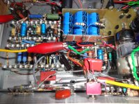
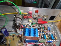
I put it all back together yesterday, not a whistle, chirp or other euphemism for oscillation. I've either done something right or the Gods feel benevolent at present.
I improved the HT decoupling - those three blue caps - and improved the ground bus. HT wise now all individual stages are de-coupled apart from the tone control hi gain stage and OP CF, which have one stage. Trying to fit all this in is a nightmare, there's plenty of room, but it's in the wrong place. One more ting, I re-jigged the tone control de-coupling too.
What the cause of the oscillation was I'm still not 100% sure - resonant HT PSU, sloppy de-coupling,iffy layout and ground bus loopyness? Anyhoo, main thing it seems to be fixed.....for now. Thanks for all your help, Andy.
This is what I've done Tom.n guitar amps (I've seen) the volume is normally after the tone stack.
I put it all back together yesterday, not a whistle, chirp or other euphemism for oscillation. I've either done something right or the Gods feel benevolent at present.
I improved the HT decoupling - those three blue caps - and improved the ground bus. HT wise now all individual stages are de-coupled apart from the tone control hi gain stage and OP CF, which have one stage. Trying to fit all this in is a nightmare, there's plenty of room, but it's in the wrong place. One more ting, I re-jigged the tone control de-coupling too.
What the cause of the oscillation was I'm still not 100% sure - resonant HT PSU, sloppy de-coupling,iffy layout and ground bus loopyness? Anyhoo, main thing it seems to be fixed.....for now. Thanks for all your help, Andy.
Attachments
- Home
- Amplifiers
- Tubes / Valves
- Power supply design - LF instabilty.