I am working on a SEP amp with the 6BG6GA tube. To regulate the screen supply, I have a pair of 0D3 VR tubes in series to provide a voltage reference to a MOSFET source follower:

It seems to work fine on the breadboard, but I have this little nagging voice in the back of my head wanting to stick a resistor between the source and ground. I know a MOSFET does not care where the ground is, as long as the drain is higher than the source, and the gate is somewhere in between. Should I stick a, say, 300k resistor from source to ground to ensure that the MOSFET is always on, or should I drown out the little voice with a bunch of fermented beverages?
It seems to work fine on the breadboard, but I have this little nagging voice in the back of my head wanting to stick a resistor between the source and ground. I know a MOSFET does not care where the ground is, as long as the drain is higher than the source, and the gate is somewhere in between. Should I stick a, say, 300k resistor from source to ground to ensure that the MOSFET is always on, or should I drown out the little voice with a bunch of fermented beverages?
Attachments
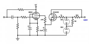
According to the specs the K5A50D MOSFET has already a built-in protective diode between source and drain. You may add a zener to protect the grid from source to grid for more safety.
So far I haven’t seen any problems with my MOSFET PSU’s (various boards from 400 to 600 VDC) without any default load. However a minimal load will not hurt much as long as you keep the MOSFET’s dissipation low and the MOSFET cooled.
Regards, Gerrit
So far I haven’t seen any problems with my MOSFET PSU’s (various boards from 400 to 600 VDC) without any default load. However a minimal load will not hurt much as long as you keep the MOSFET’s dissipation low and the MOSFET cooled.
Regards, Gerrit
Isn't 6BG6 a different 6L6?
6L6 can have negative G2 current in some part of its operating range. I'd want a bleeder for about 10% of nominal G2 current.
And seeing the minimum current of the gas tube is about the same value, I dunno what the MOSFET is really doing here.
6L6 can have negative G2 current in some part of its operating range. I'd want a bleeder for about 10% of nominal G2 current.
And seeing the minimum current of the gas tube is about the same value, I dunno what the MOSFET is really doing here.
Isn't 6BG6 a different 6L6?
6L6 can have negative G2 current in some part of its operating range. I'd want a bleeder for about 10% of nominal G2 current.
And seeing the minimum current of the gas tube is about the same value, I dunno what the MOSFET is really doing here.
Gotcha. Thanks for the tip. I guess if I had VR tubes for each screen, the shunt regulation will take care of the excessive G2 voltage when there is negative current.
The VR tubes are just serving as voltage reference for the screens of the power tubes and the drivers. There will be a separate transistor for each screen and the driver tube to cut down on cross-talk and interaction between the stages. Plus, I can slap big capacitors in there and not have to worry about making a relaxation oscillator.
I am working on a SEP amp with the 6BG6GA tube. To regulate the screen supply, I have a pair of 0D3 VR tubes in series to provide a voltage reference to a MOSFET source follower:
It seems to work fine on the breadboard, but I have this little nagging voice in the back of my head wanting to stick a resistor between the source and ground. I know a MOSFET does not care where the ground is, as long as the drain is higher than the source, and the gate is somewhere in between. Should I stick a, say, 300k resistor from source to ground to ensure that the MOSFET is always on, or should I drown out the little voice with a bunch of fermented beverages?
The output voltage at the source does vary with the load current. One way to limit this output voltage variation is to 'pre-load' the output. Your idea to add a resistor to ground is a good idea. It adds a constant current draw to the source, decreasing the relative current variation, decreasing the source output voltage variation.
Jan
You could also use zeners instead of the OD3’s and add a capacitor to prevent zener noise across each zener.
Regards, Gerrit
Regards, Gerrit
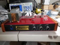
Yea, but zeners don't light up.😀 The planned layout has the rectifier tube flanked by the 0D3s, and it looks pretty cool. I got 75v zeners for the driver pentode screens, though.
Does your MOSFET have protecting diodes, like Zener for the gate and a reverse protecting diode? If not, you must add them externally.
Right, under normal conditions zeners don’t light up. However, if you abuse them, they may light up shortly 😀, I know, because I tried...
Regards, Gerrit
Regards, Gerrit
Does your MOSFET have protecting diodes, like Zener for the gate and a reverse protecting diode? If not, you must add them externally.
Yep. Gonna switch to 2SK3563. They're obsolete, but I got a stash of them. If I really want to get freaky, I'll dip into my reserve of 2SK2700.
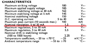
That 0D3 string needs at least 30mA just to light up.....!
Is the excursion worth the journey?
A resistor divider would do....
Is the excursion worth the journey?
A resistor divider would do....
You might want to include a source stopper resistor to head off parasitics. Connection directly to a big capacitor is potentially tricky.
All good fortune,
Chris
All good fortune,
Chris
- Home
- Amplifiers
- Tubes / Valves
- Voltage Regulator Tube with MOSFET Follower for SEP Screen Supply