Hi all
I purchased a Denon PMA-700v for parts but decided to see if I could get it working. I am a beginner in electronics and have hit my knowledge limit and was hoping someone may be kind enough to offer some suggestions.
The amp had one channel blown and I spent ages removing and testing components. I replaced the output transistors (originally 2sa1104/2sc2579) with 2sa1943/2sc5200 and driver ? Transistors 2sa1306/2sc3298 with mje15033/15032.
I powered it up with a variance and dumb bulb tester not problems. I then kept swapping higher wattage globes until I had a 1.1 amp current limit. Both channels produced great sign waves using dummy loads.
I then thought I would remove the dim bulb tester and ramped up the variance to 240v no problem. I hen turned up the volume u til I reached the previous limit using the dumb bulb tester (9.8vrms, 27vpp) with no issues. When I increase the volume some more to 12vrms R560 burns and all output transistors are killed.
ANy suggestions as to why this may be happening. I did have a relay issues that appeared to be a broken solder joint I fixed. Any help appreciated, it appears the outputs die first ?
Richard
Attachments
It could be something that coursed oscillation.
after you fix the blown components,
you need to have a thorough check on every part of your amp for open or short circuit.
bad joints, broken pads, groundings, switches, connections, cables for continuity.
transistors, resistors, capacitors, diodes, zeners,.etc.
make sure all the power supply voltages are correct on the board.
It takes time and patience.
when you have done checking and sure that the amp is all ok,
you need your variance and dumb bulb tester again,
with a dummy load (resistors)connect to the speaker output you start from small signal input.
one channel at a time, (you can disconnect the power supply on the other channel,)
don't drive the amp to full power output unless you are sure that all the problems have gone.
you need a scope to check the output waves to see if there were oscillation.
If you substituted transistors, may be a small problem.
But you must find what caused the failure.
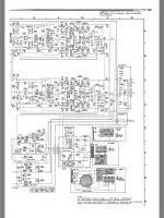
Get hold of the schematic, check the voltages mentioned.
Use the other channel for reference.
Could be over driven transistors from a defective voltage regulation stage.
But you must find what caused the failure.
Get hold of the schematic, check the voltages mentioned.
Use the other channel for reference.
Could be over driven transistors from a defective voltage regulation stage.
Many times resistors that in serial to the power rail + or -,
tend to change their values due to long time of heat, coursing bad connections, open too.
like R501, R502,R503,R504, R505,R506,R507,R508.
they are all 1W resistors.
Capacitors, they look good on the outside but already changed their values inside.
tend to change their values due to long time of heat, coursing bad connections, open too.
like R501, R502,R503,R504, R505,R506,R507,R508.
they are all 1W resistors.
Capacitors, they look good on the outside but already changed their values inside.
If the amp works OK up to a moderate output level (as per your 12V RMS test), logically that knocks out or at least reduces the chance of static faults such as bad resistors, semis, and shorts.
It's likely a dynamic fault such as instability or oscillation which may be caused by a cap. or semi anywhere in the amplifier main or feedback signal path. Use the schematic to trace the paths. IIRC, Denon also show signal paths on some schematics.
You need to be able to view or otherwise sense instability when you fire up the amplifier after a repair, whether you have dim bulb tester in use or not. Oscillation can be sensed long before it burns up transistors and this prevents repeated failures and head-scratching as to why the amplifier keeps destroying itself. You can bet that the guy who sold this had the same problem and never resolved it or maybe the repair quote scared him off.
First thing to do, I guess, is to return it to the state where you had some function but before you wind up the output this time, use a 'scope to look for wriggles on the test trace, assuming you have a suitable audio oscillator or you have the software (download Audacity - it has everything!) or one already installed on your PC.
Nowadays, an oscilloscope capable of 50-100MHz isn't the huge expense it was and a used one is even cheaper. If still too expensive, try borrowing or just getting someone else with a 'scope to help you out with their test gear.
There is a serious flaw in the design of these amplifiers (PMA-500V, 700V and 900V) and that is the lack of current limiters in the output stages. I even went as far as kludging in my own.
I always take the lazy engineer's approach in that I am lazy replacing output transistors. I make very sure the amp works up until the drivers before I put in a set of new output transistors. In the case of the 700V I short the base and emitter pads of an output transistor (eg. TR511) so that the feedback loop is closed. This way the amp is able to drive a light load like headphones. Now you can verify the bias setting (across R559/D541) and any instability using a square wave input and scope. Once this is done new transistors can be soldered in place. Your choice is OK although I would have used 2SC5242/A1962 because of the TO-3P package. And I have them in my parts tray.
I always take the lazy engineer's approach in that I am lazy replacing output transistors. I make very sure the amp works up until the drivers before I put in a set of new output transistors. In the case of the 700V I short the base and emitter pads of an output transistor (eg. TR511) so that the feedback loop is closed. This way the amp is able to drive a light load like headphones. Now you can verify the bias setting (across R559/D541) and any instability using a square wave input and scope. Once this is done new transistors can be soldered in place. Your choice is OK although I would have used 2SC5242/A1962 because of the TO-3P package. And I have them in my parts tray.
Last edited:
Thanks for the comments everyone. Based on the advice I decided to step through all the components on the subject channel replacing them if I had any doubt. I even replaced the opamps.
As per another post I made it appears the replacement transistors 2sc5200/2sa1943 were fake which didn't help.. I swapped the transistors from the other channel to the subject one and established there was still no output. I then started probing from the outputs back through both channels making comparisons as I went and found two bad solder joints around TR410 and TR414. The blown channel is now working fine with original transistors and I can get 100w output power. Lesson learnt to check all solder joints early on. I will now wait for the replacement genuine updated transistors to arrive and see how they go and report back for anyone interested. Looking forward to see how this amp sounds actually.
As per another post I made it appears the replacement transistors 2sc5200/2sa1943 were fake which didn't help.. I swapped the transistors from the other channel to the subject one and established there was still no output. I then started probing from the outputs back through both channels making comparisons as I went and found two bad solder joints around TR410 and TR414. The blown channel is now working fine with original transistors and I can get 100w output power. Lesson learnt to check all solder joints early on. I will now wait for the replacement genuine updated transistors to arrive and see how they go and report back for anyone interested. Looking forward to see how this amp sounds actually.
Replaced output transistors with genuine 2sc5200n and 2sa1943 and amplifier is working. I will stress test it for a while but all seems fine thus far. Thanks everyone. This amp has some nice components incl sought after 2sk170 FETs.
Very rewarding getting an amp going again as a beginner.
Very rewarding getting an amp going again as a beginner.
- Home
- Amplifiers
- Solid State
- Denon PMA-700v repair help