I want a project to keep me busy for a week or so but I'm getting slightly overwhelmed by all the options available so I thought I'd start a new thread to collate all my options.
- I have IEMs, planars and dynamics so ideally it can drive all of those, but being able to drive planars and dynamic cans is a must whereas IEMs are optional.
- Something more powerful than my current Atom amp would be very nice, especially as I want to power hard to run planars.
- I want something fully discrete as the Atom is opamp-based.
- Class A would be nice but not necessary.
- Since I live in Hong Kong, getting a cheap chassis from taobao isn't a problem, so there's no need to set aside too much money for that.
- I have a hot air gun and know how to do SMT soldering.
- Nothing too expensive please, I'm a student!
Last edited:
It appears that the most difficult headphones to drive in the whole wide world, are the Hifiman HE-6 (citation). In order to produce 110dB SPL, the HE-6 requires an input signal whose amplitude is 11.2V RMS. Headphone impedance is 43 ohms so the amplifier must drive 0.26 amperes RMS into the HE-6. A bit of calculator work tells us: 11.2V RMS is 15.8V peak, and 0.26 amps RMS is 0.37A peak.
Give yourself some headroom for transistor VBE drops, Remitter drops, and to be prepared for future, even-harder-to-drive, headphones: choose ±24V power supply rails. Then design a ±24V DC power supply capable of providing at least 0.75A per stereo channel. There you go: lots of safety margin.
Now just build yourself a cookbook "Blameless" audio power amplifier using discrete transistors, copied straight out of Douglas Self's textbook. Bias your push pull output stage in the Class-A regime, with an idle current of 0.2 amperes. This OPS will exit class-A and enter class-AB when the output current exceeds two times the idle current, namely at 0.4 amps. Even the Hifiman HE-6 doesn't require 0.4 amps, so you're guaranteed to operate in Class-A all the time, with all headphones.
You'll need to build your amp using power transistors, and mount them on a heatsink, since the output devices will dissipate more than 10 watts. If you prefer to build the driver and output stages using some really high fT devices in the "medium power" TO-126 package, perhaps such as KSA1220AY + KSC2690AY, maybe you'll want to have two in parallel (with equalizing resistors!) to manage the heat.

Looks interesting, I'm considering this one or P113 from ESP 🙂
P113 is a basically like the "earle eaton amplifier" from head-fi.org which I built many years ago.
It was one of the best headphone amps I built although I didn´t know much about PCB design then. Difference to other amps was mainly a very pronounced bass definition. I´d build it again over let´s say opamp+BUF634 which is not bad but an output stage like the above is plenty IMHO.
Opamp used was a NE5534.
Hard to go wrong with a simple composite for headphone amps I´d say although I´m pretty sure Bonsai´s design is at least as good.
Last edited:
Ah was just wondering because that comment had kind of a negative understone to it...though I'm definitely leaning towards Bonsai's design as P113 is very old and while I don't doubt how it sounds, I like SMT soldering a lot 😛
I made a Naim clone, sounds very good into my Audeze LCD2.2s, see here:
Headline clone | pink fish media
Headline clone | pink fish media
Here is one by Mediatechnology (Bill Kirkwood) that is nominally 3W but can be boosted to 10w Class A using DRV134 or THAT1646 as driver.
Simple Class A Headphone Amp Using THAT1646

Simple Class A Headphone Amp Using THAT1646
That looks pretty interesting too! Something to consider for sure. It looks like it would require pretty substantial heatsinking but that's normal for higher-powered class A stuff. Thanks for the rec 😀
Excellent work Dear!!!I made a Naim clone, sounds very good into my Audeze LCD2.2s, see here:
Headline clone | pink fish media
Also PCBs Headline 2 from hifidiy portal design
Attachments
Hi There...................
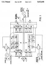
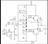
Here is a little amp that may be suitable for your needs, I had a lot of fun with it, and it sounded great when I had the outputs well into a class a state of bias as described in the thread !!! 😉 😀
It drove a 2 ohm just fine up to about half the supply voltage and would swing as far as the opamp would go at anything above 16 ohms.
I used every thing I had in this circuit from LT's to LME49860/720' and such, they all worked.
Surprisingly I found out (as I was still learning stuffat the time..... we never stop do we) is that you only need to change the value of one of the resistors to adjust the output current through the two devices.
I had matched up the diodes but it is not needed to be done to make it work and I still have them in a little bag somewhere as I had planned on using this as a HP/Bench utility amp as well sometime when I get to making some PCB's soon.
Cheers !!!
jer 🙂
https://www.diyaudio.com/community/threads/strange-problems-with-transistors.252027/post-3837607
Attachments
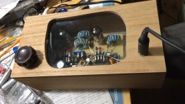
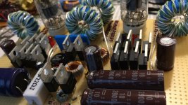
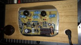
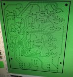
Headphone amplifier with digital volume control
Power output about 3W
also I make 5w amp but 3W sound is better
Power output about 3W
also I make 5w amp but 3W sound is better
Last edited:
Wow this very power schematic with operational amplifierHi There...................
Here is a little amp that may be suitable for your needs, I had a lot of fun with it, and it sounded great when I had the outputs well into a class a state of bias as described in the thread !!! 😉 😀
It drove a 2 ohm just fine up to about half the supply voltage and would swing as far as the opamp would go at anything above 16 ohms.
I used every thing I had in this circuit from LT's to LME49860/720' and such, they all worked.
Surprisingly I found out (as I was still learning stuffat the time..... we never stop do we) is that you only need to change the value of one of the resistors to adjust the output current through the two devices.
I had matched up the diodes but it is not needed to be done to make it work and I still have them in a little bag somewhere as I had planned on using this as a HP/Bench utility amp as well sometime when I get to making some PCB's soon.
Cheers !!!
jer 🙂
https://www.diyaudio.com/community/threads/strange-problems-with-transistors.252027/post-3837607
- Home
- Amplifiers
- Headphone Systems
- High-powered headphone amps