Ok, let’s start with assumptions…………….
Assume a 3” with a flat impedance out to 20k, say 5 ohms.
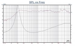
The driver itself drops 5db or so past 5khz (some tang bands and fostex).
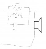
So add some baffle step (resistor and inductor paralleled together), put that in series with the driver.
So, can I add a small cap to that circuit to bring back some highs past 5khz ?
I read something on it years ago………………….
Assume a 3” with a flat impedance out to 20k, say 5 ohms.
The driver itself drops 5db or so past 5khz (some tang bands and fostex).
So add some baffle step (resistor and inductor paralleled together), put that in series with the driver.
So, can I add a small cap to that circuit to bring back some highs past 5khz ?
I read something on it years ago………………….
Attachments
Hi,
Sure. This is what needs to be done to most widerange drivers if you want a balanced representation.
All the best
Mattes
Sure. This is what needs to be done to most widerange drivers if you want a balanced representation.
All the best
Mattes
Last edited by a moderator:
Yes and no. Once you put a cap in parallel with an inductor, it will have a resonant frequency where impedance shoots up. You need to check when that happens.
Oon
Oon
Last edited:
Ok, let’s start with assumptions…………….
Assume a 3” with a flat impedance out to 20k, say 5 ohms.
The driver itself drops 5db or so past 5khz (some tang bands and fostex).
So add some baffle step (resistor and inductor paralleled together), put that in series with the driver.
So, can I add a small cap to that circuit to bring back some highs past 5khz ?
I read something on it years ago………………….
As in convert a parallel LR shelving filter into a parallel notch? Sure. As always, select values as appropriate to a give design (frequency and impedance -you may need to add a series RC Zobel shunt to ensure it works properly -it's not always possible to hit the desired response without as in many cases you'll also have the rising VC impedance to contend with).
As said in other words adding the cap changes the shelf at HF to a (usually broad) suppression in the middle ranges), allowing the highest frequencies to pass the filter.
This causes an effective lift at top and bottom, and is an old trick i learned from Henry Kloss. He would use the circurt to give drivers like those used in the Bose 901 have top & bottom. He used it to get decent LF & HF balance in the Advent 400.
I had to use it once with dome dirt cheap 8” whizzered FRs. Later swapped in SEAS FA22eN and lost the circuit :^)
dave
Bose used a passive series filter to make the 101 series listenable. Released ~1980 it used a driver similar to 901/802. I've often copied the idea to improve the performance of small speakers, such as the Tannoy CPA-5. 5.6Ω//6.8µF//0.56mH knocks 3dB off an objectionable bump centred on 1.9kHz, the Q of the filter tuned to the Q of the bump.This causes an effective lift at top and bottom, and is an old trick i learned from Henry Kloss. He would use the circurt to give drivers like those used in the Bose 901 have top & bottom.
Of course Tannoy have used tuned filters to correct their coaxial horn responses for yonks.
Last edited:
I used similar tricks also to flatten out driver response of fullrange drivers, but always do it on measured response in the box, not just guessing or the result can be way off and worse than without the filter. Idem with BSC, sometimes it's needed, but not always, so rely on measurements before adding it.
Hi,
Exactly. Only measurements will show what you´re doing and your circuits must be matched to your drivers and boxes. Measurements will also show the influence of value variations of each part.
Once your measurements are showing that your results are more or less OK, than use your ears for final finetuning.
For a quality driver part quality compromises should be avoided.
All the best
Mattes
Yes and no. Once you put a cap in parallel with an inductor, it will have a resonant frequency where impedance shoots up. You need to check when that happens.
There are RC, LC, LR, LCR and other serial resonant circuit variants. But no, in this case, the C bypasses the LR circuit, so it lowers the increased impedance of the LR circuit in the upper f-range, but not below the impedance of the driver. Why? Because it bypasses the LR circuit on high frequencies.
As said in other words adding the cap changes the shelf at HF to a (usually broad) suppression in the middle ranges), allowing the highest frequencies to pass the filter.
That's ofcourse correct. Just to clear things up, the LR filter is a negative shelf and the bypass C poses a positive shelf EQing.
This causes an effective lift at top and bottom, and is an old trick i learned from Henry Kloss. He would use the circurt to give drivers like those used in the Bose 901 have top & bottom. He used it to get decent LF & HF balance in the Advent 400.
This trick is over 70 years old, EV, GE, Altec and others already used it very early on.
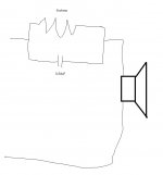
or maybe use a resistor / cap to flatten out this driver past 5khz...………. (no baffle step)
Assuming 9ohms (yes, I know it is climbing), maybe a 3.54uF (9ohm making for -3db@5khz ballpark)
You can introduce a parallel circuit (CR) to keep the impedance flat. The impedance correction and bypass C are things you really should know already though.
Ok, let’s start with assumptions…………….
Assume a 3” with a flat impedance out to 20k, say 5 ohms.
The driver itself drops 5db or so past 5khz (some tang bands and fostex).
So add some baffle step (resistor and inductor paralleled together), put that in series with the driver.
So, can I add a small cap to that circuit to bring back some highs past 5khz ?
I read something on it years ago………………….
Yes, you can do that. The capacitor goes parallel to the LR filter.
You can introduce a parallel circuit (CR) to keep the impedance flat. The impedance correction and bypass C are things you really should know already though.
To clarify: That needs serial parts for the voltage drop, otherwise it just draws more current from the amplifier.
Not as simple as that because the current for the coil and and capacitor is 180 degree out of phase. So at the point where their impedance match each other there will be no current flowing as they cancel out each other and that will be the resonant frequency. Resulting in an infinite impedance and total impedance will shoot up and will be determined by the R instead.There are RC, LC, LR, LCR and other serial resonant circuit variants. But no, in this case, the C bypasses the LR circuit, so it lowers the increased impedance of the LR circuit in the upper f-range, but not below the impedance of the driver. Why? Because it bypasses the LR circuit on high frequencies.
That's ofcourse correct. Just to clear things up, the LR filter is a negative shelf and the bypass C poses a positive shelf EQing.
This trick is over 70 years old, EV, GE, Altec and others already used it very early on.
You can introduce a parallel circuit (CR) to keep the impedance flat. The impedance correction and bypass C are things you really should know already though.
Yes, you can do that. The capacitor goes parallel to the LR filter.
https://www.electronics-tutorials.ws/accircuits/parallel-resonance.html
You can still do it, just be mindful that there might be a sudden peak in impedance somewhere. It may or may not happen depending on the values that you choose and it might be limited by the R.
Oon
Oon
Not as simple as that because the current for the coil and and capacitor is 180 degree out of phase. So at the point where their impedance match each other there will be no current flowing as they cancel out each other and that will be the resonant frequency. Resulting in an infinite impedance and total impedance will shoot up and will be determined by the R instead.
https://www.electronics-tutorials.ws/accircuits/parallel-resonance.html
While that is true, this is a serial circuit, not a parallel/suction circuit!
I'm going to use the 9ohm/3.5uF to help the fe87 (post 11) past 5khz...…………..
(well, basically turning down stuff under 5khz anyway)
(well, basically turning down stuff under 5khz anyway)
Attachments
Last edited:
You can refer to first post. It is a parallel circuit.While that is true, this is a serial circuit, not a parallel/suction circuit!
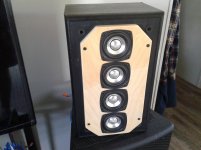
Sucess !!!!!!
3uf + .47uf + 9ohms (got screwed, no 9ohm resistors, so 2 x 4.5ohm in series).
I use it as a vocal monitor, understanding movies late at night.
Not really great at music, but never intended to be.
I am up for selling this.
Reinforced front baffle, added acoustuf, professionally soldered, sealed.
Send email here if interested.
Otherwise I'll put it on swapmeet forum here sunday night
I have a builder here working on a 9 driver focused array, learning from my last one.
Attachments

Last edited:
- Home
- Loudspeakers
- Full Range
- Bypass passive bsc with cap ?