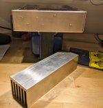
I'm looking for some advice on the best (and most straightforward) way to mount some aluminum heatsinks to a Hammond enclosure for a tube headphone amplifier project I built.
The enclosure is a 9" x 7" x 2" Hammond enclosure and the heatsinks are 2" x 7" extruded aluminum.
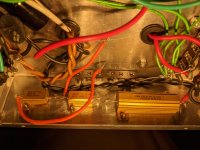
There are some power resistors mounted to the side of the enclosure with M2 screws and nuts, which protrude from the side (see pictures).
Seems like I have 3 options, would like opinions as to which is the way to go. I have a drill press and some M2 and M3 taps, but I am NOT an experienced machinist, so I'm looking to try to keep the driling and tapping complexity to a minimum.
Does this make sense? Any advice? I'm leaning toward the thermal epoxy route as it seems to be the easiest approach but I have never worked with it before, so I really don't know.
I'm concerned that my drilling and tapping skills will be put very much to the test if I go another way but I'm willing to try 😉.
The enclosure is a 9" x 7" x 2" Hammond enclosure and the heatsinks are 2" x 7" extruded aluminum.
There are some power resistors mounted to the side of the enclosure with M2 screws and nuts, which protrude from the side (see pictures).
Seems like I have 3 options, would like opinions as to which is the way to go. I have a drill press and some M2 and M3 taps, but I am NOT an experienced machinist, so I'm looking to try to keep the driling and tapping complexity to a minimum.
- Drill some oversized holes for the screw heads to slot into the heatsinks and mount them to the side of the project enclosure with thermal epoxy. This seems like it requires the least amount of precise drilling and tapping. The downside is that they are then permanently attached and removing the power resistors later down the line becomes difficult.
- Drill some oversized holes for the screw heads to slot into the heatsinks and then drill and tap four (M3? M4?) holes at the corners of the heatsink and project enclosure. Use bolts to attach the heatsink to the side of the enclosure. This will require me to do a fair amount of internal disassembly so I can fit a tool inside the enclosure to actually fasten the bolts once the holes are drilled.
- Drill and tap the four aforementioned holes in the heatsink and enclosure AND drill and tap holes for the power resistors in the heatsink. Mount the heatsink to the side of the enclosure and then mount the power resistors to the heatsink with the screws passing through the existing holes in the enclosure.
Does this make sense? Any advice? I'm leaning toward the thermal epoxy route as it seems to be the easiest approach but I have never worked with it before, so I really don't know.
I'm concerned that my drilling and tapping skills will be put very much to the test if I go another way but I'm willing to try 😉.
Attachments
First thoughts it doesn't seem right that these two surfaces will stay true with bolting (although the epoxy does seem interesting). Have you considered removing the side and replacing it with the heatsink itself?
Having a sandwiched panel between a device that needs cooling and the heatsink is not ideal.
I would section out the side with a nibbler or jigsaw so that the mounting surface of the heatsink is exposed inside the case.
Then drill between the fins and bolt the heatsink to the side panel in the four corners.
Drill and screw the power resistors directly to the heatsink with self tapping (thread cutting) screws.
Use a silicon heat transfer pad under the resistors (optional).
These are great suggestions. Mounting the resistors directly to the heatsink should be straightforward given that I can mount them prior to attaching the heatsink to the (nibbled/and or jigsawed) side of the enclosure.
Quite a big heat sink for a headphone amplifier. How hot does the resistors get on the current chassis? I see 30W, 10W and 10W resistors.
Don't want the amp to smoke before your ears do! Actually it's a valve amp, by the look of it.
It does remind me once on tour in 1983 with the musical Me & My Girl when I had to rapidly find a solution to an drummer in the orchestra pit who needed to hear a vocal on stage. I hastily rigged some headphones from the nearest consumer electronics store to a spare foldback send. Part way into the next rehearsal the drummer caught my eye waving a thumbs up, just as I noticed smoke wafting over his head from out of the earpieces.
It does remind me once on tour in 1983 with the musical Me & My Girl when I had to rapidly find a solution to an drummer in the orchestra pit who needed to hear a vocal on stage. I hastily rigged some headphones from the nearest consumer electronics store to a spare foldback send. Part way into the next rehearsal the drummer caught my eye waving a thumbs up, just as I noticed smoke wafting over his head from out of the earpieces.
If you can find it use a piece of carbon paper to transfer the bolt heads location onto the heat sink. Now you can drill shallow clearance holes for the heads. Then drill four mounting holes in the heatsink and match them on the chassis.
Not really an issue with the thermal resistance with that much common surface area.
If you can't find carbon paper, line up the heatsink exactly where you want it and tap with a hammer to put marks where the bolt heads are. To avoid damage to the heatsink use a block of wood across the fins to spread and soften the hammer blow.
How hot does the resistors get on the current chassis? I see 30W, 10W and 10W resistors.
It gets uncomfortably hot to the touch. Something like 58*C on the side of the chassis where the power resistors are mounted, once the amp has been running for a while.
If you can find it use a piece of carbon paper to transfer the bolt heads location onto the heat sink.
Another great suggestion, thank you!
It does remind me once on tour in 1983 with the musical Me & My Girl when I had to rapidly find a solution to an drummer in the orchestra pit who needed to hear a vocal on stage. I hastily rigged some headphones from the nearest consumer electronics store to a spare foldback send. Part way into the next rehearsal the drummer caught my eye waving a thumbs up, just as I noticed smoke wafting over his head from out of the earpieces.
This made me lol -- thankfully no smoking headphones thus far. Just a really, really inefficient tube amplifier / room heater.
You have 2 x 150 ohm resistors in series therefore dissipating the same power?
Yet one is 3 x the size of the other.
Is this to use parts you had available?
Yet one is 3 x the size of the other.
Is this to use parts you had available?
You have 2 x 150 ohm resistors in series therefore dissipating the same power?
Yet one is 3 x the size of the other.
Is this to use parts you had available?
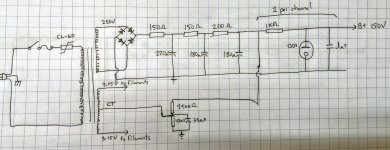
Each resistor is one stage of a 3-stage RC filter to deal with the ripple in front of an 0D3 voltage regulator tube.
When I was initially spec'ing out these resistors I based my order on the LTspice sim which overstated the dissipation probably due to the inrush current of the capacitors charging at turn-on.
I took some real measurements just now -- once the capacitors have charged the resistors are only dissipating ~3-4W continuously. That said, at turn on I measured the first resistor momentarily dissipating ~20W. The resistors are rated at 30W, 15W, and 10W, respectively.
Still learning as I go.
I've attached the power supply schematic for your perusal.
Attachments
All three resistors have the same average current (Idc) flowing through them. So the 2 x 150Ω will dissipate the same power steady state, and the 200Ω one 25% more.
The AC ripple currents will diminish from input to output, but the ripple current have ±values centred on the average and don't affect the average current. In other words the ripple currents don't cause any additional power dissipation; only the average current value is important for power dissipation P = Iaverage x R.
The AC ripple currents will diminish from input to output, but the ripple current have ±values centred on the average and don't affect the average current. In other words the ripple currents don't cause any additional power dissipation; only the average current value is important for power dissipation P = Iaverage x R.
Yup, I went overkill on the size of them. Lesson learned.
Btw I took some additional temperature measurements after running the amp for maybe 20 mins or so. The side of the chassis with the power resistors reached 65°C and the opposite side, where the cathode resistors for the 5687 tube are mounted, reached 52°C. Hence the need for the heatsinks.
Btw I took some additional temperature measurements after running the amp for maybe 20 mins or so. The side of the chassis with the power resistors reached 65°C and the opposite side, where the cathode resistors for the 5687 tube are mounted, reached 52°C. Hence the need for the heatsinks.
- Home
- Design & Build
- Construction Tips
- Mounting aluminum heatsinks to Hammond enclosure