Hi
i need help for phoenix gold ms2250 with "pop" on the right channel.
i don't have this pop on the first start, but if power off, and restart, i have this pop. if i wait big rail capacitors discharge, i don't have the pop.
i have notated big capacitors of the power supply on the right channel don't discharge fastly like left channel, but this situation can be normal because +-15V on the left channel is OP-amp power supply, right?
What can i check?
MS2250
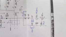
Change Q312 to an MPSA12, watch pin outs.
Replace C301 with a new 105C type 47mfd 16v/25v
From pin 1 of OP302 connect a 1K 0.5w to power supply ground. This will be the discharge for C301.
Change R301 from 4K7 to 470K for about 2.5 sec delay, 820K for 4 second delay.
Solder a 1N4148 diode across R301 cathode to OP302 pin 1... this is the discharge path for C301. Make sure 1N4148 soldered right way.
Now you will have a repeatable turn on cycle with no pops and thumps.
Solder 6K8 2 watt across each of the 6,800mfd 63v main caps.
There are separate +/-15v supplies for each channel
Regards
Steve Mantz
Zed Audio
MS2550
These optocouplers control the differential constant current sources on and off functions.
It is important to delay these diff amps turn on as long as possible until the opamps upstream have time to setlle down.
These are old amplifiers and do really need all the large electrolytics to be changed especially those on the 12v side of the power supply.
I do a lot of PG service and these "12v" capacitors are always leaky.
One issue that every car amplifier has (except those I design for companies) is that on turn off, the power supply turns off immediately thus the amplifier circuits are at the mercy of the discharge of all the various electrolytics.
I do it a little differently.
I keep the power supply fully on for about 2 seconds after the remote turn on is turned off. My control systems are driven from the remote terminal and they detect the presence of voltage. When the voltage drops to zero = turn off, I immediately power off the main amplifiers (Class B or D) and then 2 seconds later allow the PSU to turn off. In this way no discharge of any big caps can interfere with the turn off of the main amps.
Yes, i have changed all capacitors on the maiboard for this problem. I will make this mod and let you know if i solve the problem, thanksThese optocouplers control the differential constant current sources on and off functions.
It is important to delay these diff amps turn on as long as possible until the opamps upstream have time to setlle down.
These are old amplifiers and do really need all the large electrolytics to be changed especially those on the 12v side of the power supply.
I do a lot of PG service and these "12v" capacitors are always leaky.
One issue that every car amplifier has (except those I design for companies) is that on turn off, the power supply turns off immediately thus the amplifier circuits are at the mercy of the discharge of all the various electrolytics.
I do it a little differently.
I keep the power supply fully on for about 2 seconds after the remote turn on is turned off. My control systems are driven from the remote terminal and they detect the presence of voltage. When the voltage drops to zero = turn off, I immediately power off the main amplifiers (Class B or D) and then 2 seconds later allow the PSU to turn off. In this way no discharge of any big caps can interfere with the turn off of the main amps.
Change Q312 to an MPSA12, watch pin outs.
Regards
Steve Mantz
Zed Audio
I'm sorry Steve, can i use ksp13 instead Mpsa12? I don't found this transistor
PG
OK simply adjust the value of the 820K for whatever time delay you want.
My simulator shows 47mfd + 820K on a 12v supply gives about 4 seconds until the Vbe of the darlington reaches 1.2 volts.
OK simply adjust the value of the 820K for whatever time delay you want.
My simulator shows 47mfd + 820K on a 12v supply gives about 4 seconds until the Vbe of the darlington reaches 1.2 volts.
Did you install the 6.8k resistors?
Yes, but don't discharge the rail capacitors..
How long do the rail caps stay at the full rail voltage with and without the resistors installed?
PG
Make sure that the opamps in front of the main amplifiers are 100% stabilized BEFORE the differentail amps are allowed to power up.
One issue with these power amplifier blocks is that they are inverting and this is also a negative....no way to change this without extensive surgery to the PCB.
Also try to increase the 22 ohm degeneration diff amp resistors to about 220 ohm.
Also try adding slow down capacitors across the series diodes in the constant current sources of the diff amps.
Maybe 100-470mfd per diode pair.
I have notated one strange thing on right channel. I try to explane.
When i power on this amplifier, before led202 and led201 power on, on the right channel output, i have dc voltage 2vdc, when led202 and 201 power on, This voltage goto 0V. Can be the problem? The left channel don't have dc voltage on the speaker output
In edit: 2vdc without speaker, 0.3Vdc with 4ohm speaker
Last edited:
PG
Then you have bad transistors in your diff amps and/or the VAS devices with their Darlington pre drivers.
Then you have bad transistors in your diff amps and/or the VAS devices with their Darlington pre drivers.
- Home
- General Interest
- Car Audio
- Phoenix Gold MS2250 right channel bump