Hello all!
I've been given a NAD C315BEE by a friend on the vague hope to repair it. From my diagnosis there is a distortion/muffled sound on some sounds. It's much more noticeable when the music has more sounds (ie. playing a sequence of sine waves from a youtube video from 10Hz to 20K Hz does not cause a problem).
All the inputs suffer from the problem, so I ruled out the input multiplexer circuit. The problem is also consistent across the full volume range so I also ruled out the power amplifier. Also, it happens on both channels.
I'm very dumb in terms of electronics but I started poking around and decided to test the voltages provided by the PSU board. From my tests the multiple voltages provided by the PSU board are ok (-45/+45V; 8V).
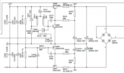
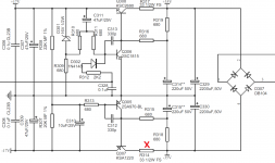
I then turned my attention to the +17V/-17V circuit (service manual, page 17) I noticed that the +17V rail is OK BUT the -17V is reading -1V ! (Amp on, no speakers connected, no inputs). Also the 5V regulator is working fine. I took the measurements between J169 (DGND) and J13 for +17V and J90 for -17V
For reference:

I measured +35V and -35V on the right side of the circuit, so that rules out the big capacitors after the full bridge rectifier. So, this leaves me with the -17V rail and I'm at the limit of my electronics skills here 🙁
I removed C330 and C315 for ease of access which appear ok (I'm unable to measure 2220uF with my meter but since the -35V rail is OK the cap should be ok too).
I then removed the capacitors from the left side: C308, C309, C310. All checkout fine. I finally removed the Q305 transistor but I'm unsure how to test it.
So, I would like to ask for your assistance. What can I test, is there an obvious culprit for the missing -17V? Should I replace all the bottom transistors ? (Q305, Q307)? Should the top part components also be replaced?
Something appears shorted here but then again I'm measuring -1V between the -17V rail and GND which (I think) rules out that possibility
Thanks!
I've been given a NAD C315BEE by a friend on the vague hope to repair it. From my diagnosis there is a distortion/muffled sound on some sounds. It's much more noticeable when the music has more sounds (ie. playing a sequence of sine waves from a youtube video from 10Hz to 20K Hz does not cause a problem).
All the inputs suffer from the problem, so I ruled out the input multiplexer circuit. The problem is also consistent across the full volume range so I also ruled out the power amplifier. Also, it happens on both channels.
I'm very dumb in terms of electronics but I started poking around and decided to test the voltages provided by the PSU board. From my tests the multiple voltages provided by the PSU board are ok (-45/+45V; 8V).
I then turned my attention to the +17V/-17V circuit (service manual, page 17) I noticed that the +17V rail is OK BUT the -17V is reading -1V ! (Amp on, no speakers connected, no inputs). Also the 5V regulator is working fine. I took the measurements between J169 (DGND) and J13 for +17V and J90 for -17V
For reference:
I measured +35V and -35V on the right side of the circuit, so that rules out the big capacitors after the full bridge rectifier. So, this leaves me with the -17V rail and I'm at the limit of my electronics skills here 🙁
I removed C330 and C315 for ease of access which appear ok (I'm unable to measure 2220uF with my meter but since the -35V rail is OK the cap should be ok too).
I then removed the capacitors from the left side: C308, C309, C310. All checkout fine. I finally removed the Q305 transistor but I'm unsure how to test it.
So, I would like to ask for your assistance. What can I test, is there an obvious culprit for the missing -17V? Should I replace all the bottom transistors ? (Q305, Q307)? Should the top part components also be replaced?
Something appears shorted here but then again I'm measuring -1V between the -17V rail and GND which (I think) rules out that possibility
Thanks!

More likely to be an open than a short. You can check a transistor as two diodes.
Also check the resistor values.
Also check the resistor values.
Last edited:
More likely to be an open than a short. You can check a transistor as two diodes.
Also check the resistor values.
Will do. The transistor I pulled out has a diode drop of 0,6V BE and CE. Should be ok.
Can I test resistors in circuit or do I need to dessolder them?
Also check the transistor Rce both ways with the diode function, it should be very high.
Sometimes transistors can fail with a CE short, and yet still the BE and CE diodes will test ok.
Start by testing the resistors in circuit.
What's the DC volltage across C310? Should be small, around -2V.
Sometimes transistors can fail with a CE short, and yet still the BE and CE diodes will test ok.
Start by testing the resistors in circuit.
What's the DC volltage across C310? Should be small, around -2V.
Last edited:
Also check the transistor Rce both ways with the diode function, it should be very high.
Sometimes transistors can fail with a CE short, and yet still the BE and CE diodes will test ok.
Start by testing the resistors in circuit.
What's the DC volltage across C310? Should be small, around -2V.
Thanks for the help Rayma. I noticed that R314 is open (reading 11MOhm in circuit) when it should be 33Ohm. Wasn't expecting a resistor to fail!
I don't know if I should measure that voltage across C310. I took out all of those capacitors (C308, C309, C310) and also Q305 for testing so I'm guessing that I need to solder everything back to get proper results across C310 right?
I noticed that R314 is open
I don't know if I should measure that voltage across C310.
This may be the only problem, so button it up and see. No way of telling what the circuit would do
if you apply power with other missing parts, it could oscillate, etc. Don't do that, just reinstall everything.
The voltage on C310 makes the two 17VDC supplies track together.
Last edited:
Same with post 3 and 4. This must be because op is still under moderation.
Yes I’m sorry for the confusion. The time the posts take to get approved also varies :/
This may be the only problem, so button it up and see. No way of telling what the circuit would do
if you apply power with other missing parts, it could oscillate, etc. Don't do that, just reinstall everything.
The voltage on C310 makes the two 17VDC supplies track together.
Well I have bad news.
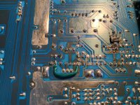
I replaced R314, C309 (both open, very close together) and also C315 with a new cap (since always very close to the first two on the board). I checked extensively with a continuity meter to check for shorts on the PCB since it's very old and some of the top layers are peeling off. I add to add a jumper to recover a lost track.
I did not pay attention that R314 was a FS resistor and replaced with with a non-fusible resistor.
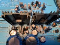
When turning on I got smoke on R314 and also on the Left channel amplifier part of the circuit. I'm unsure which component smoked on the amplifier part since I took the power out immediately. There is a FS resistor and capacitor in very close proximity. The resistor appears OK and the capacitor is charred on the side near the resistor. (I can add that part of the schematic if relevant).
Back to R314 on the power supply: I'm forced to assume that if R314 burned again it means that there's some problem that caused it to fuse in the first place. Just by replacing the resistor I was just fixing the consequence not the cause.
I don't know what to do. There's over current at R314. This is just after the bridge rectifier. Could it be that some of the transistors (Q307, Q305) are shorting a path to ground?
Do you have any pointers you could suggest me? BTW, I now have to replace an FP resistor. What's the difference between an FS and FP resistor? Don't want to make the same mistake again...
I'm adding a picture of that part of the circuit to show how awfully close these components are all together
Attachments
Last edited:
Yes, the transistors could be shorted, or else C309/C310 could be shorted.
Unplug power, use DVM in diode test mode, check Q305/Q307 in forward and reverse direction.
If no bad semis, could also be an excessive load on the output of the -17V supply.
FP = flame proof
Unplug power, use DVM in diode test mode, check Q305/Q307 in forward and reverse direction.
If no bad semis, could also be an excessive load on the output of the -17V supply.
FP = flame proof
Last edited:
Hello. Did you resolve this? I have the same fault except on the right side cluster with R317 burning. Thanks for any pointers.
- Home
- Amplifiers
- Solid State
- Help repairing a NAD C315BEE (-17V line missing)