I am playing around with the 829B and am trying to address the imbalance between sections without adding a -Vg1 bias supply.
I set up a resistor to zener reference (5.6V) in parallel with a pot to adjust the bias point of one half the tube and adjusted Vg of the low current section up to balance the two halves.
It seems that whether I use a negative bias or positive bias I still end up with the same issue that one tube is going to go into cutoff before the other due to the difference in bias voltage.
It took 1.7V of bias trim to balance the two sections of the tube I am working with which without trim had 26mA in one section and 14.7mA bias in the other.
Any thoughts on this approach over fixed bias?
Attachments
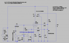
For those not familiar with the 829B, it is a twin Beam Power Tube. As such it has a common cathode and common G2 for both sections.
It was designed as an RF power amplifier up to 250MHz as well as an AF Power amplifier & Modulator.
The common cathode and G2 place restrictions on what can be done with the tube. I have only shown one section in the LTSpice schematic meant to represent the bias adjustment scheme.
https://frank.pocnet.net/sheets/049/8/829B.pdf
Last edited:
i find the 5894 to be better if you want section balance, since it has a common cathode for both sections....red plating in one section is what i experienced with the 829b....
i think it was SY who proposed, adjusting the heater voltage since this can be done in the 829b filaments...the side that is hogging more current should have its filament shaved off a bit...
i think it was SY who proposed, adjusting the heater voltage since this can be done in the 829b filaments...the side that is hogging more current should have its filament shaved off a bit...