Here's a question for the EMI/HF people out there:
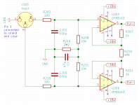
If I have a balanced line input stage like shown in the schematic below - do I want to have "CX" in there or not?
Bruno Putzeys makes a strong point for high common mode input impedance in his article "The G-Word" (https://www.diyaudio.com/archive/bl...d1460406090-bruno-putzeys-micropre-g-word.pdf , page 7). My question is:
Is that true also for the MHz range and above, where the CMRR of the input opamps will degrade, when frequencies start to rise? Wouldn't it be better if HF junk including common mode HF stuff is tied to the ground plane nearest to the input jack's ground pin, which in turn is connected to the chassis? That way those HF currents would have very short loops inside the case.
Attachments
Well, no comments means I will have to answer my own question. Upon further thinking I came to the conclusion that C202 and C203 should already do the job for common mode EMI as well as everything will be shorted to GND.
If that's incorrect there's still time to correct me 🙂
If that's incorrect there's still time to correct me 🙂
CX will not keep high frequency trash from entering the opamps. There are 10k resistors between CX and the opamp inputs.
> If I have a balanced line input stage like shown in the schematic below - do I want to have "CX" in there or not?
Like drawn, no, it's in the wrong place.
Correct place for CX is like this. You can use larger value for Cy and the fact there is only one Cx reduces imbalance in capacitor value between both signals of your differential signal, which improves CMRR.
> Bruno Putzeys makes a strong point for high common mode input impedance in his article "The G-Word"
Yes, look page 9 of THAT1200 datasheet. They bootstrap the X capacitors using the common mode signal, so their common mode impedance at audio frequency becomes very high. But they are tied to ground via the X capacitor, so at HF they work.
> Wouldn't it be better if HF junk including common mode HF stuff is tied to the ground plane nearest to the input jack's ground pin, which in turn is connected to the chassis? That way those HF currents would have very short loops inside the case.
Yes, RF to chassis ground. Keep it out of your circuit.
OK, thanks very much for the feedback! So first of all, I obviously had a somewhat correct idea but miserably failed at the implementation 🙂
@peufeu: This is the input stage for our power amplifiers. It will most likely be directly connected to the active LPF stage of a DAC which should have common mode voltage very close to GND levels (only a very small DC offset, probably <1mV). Does it make sense to derive the CM for bootstrapping the X capacitors in this case? Or is it neglible and the X-caps can go directly to GND?
@peufeu: This is the input stage for our power amplifiers. It will most likely be directly connected to the active LPF stage of a DAC which should have common mode voltage very close to GND levels (only a very small DC offset, probably <1mV). Does it make sense to derive the CM for bootstrapping the X capacitors in this case? Or is it neglible and the X-caps can go directly to GND?
I would replace R208,211,209 & CX by 2x2meg resistors - which I assume to work the same way as your circuitry. Besides there are 2x100pF for RF-suppression.
Perhaps there is no need for such high impedance - or will you connect a hi-z passive electric guitar directly into the PA-input?
So I think you may reduce input impedance between 10~100k and you can increase blocking caps from 100p to 1nF.
Perhaps there is no need for such high impedance - or will you connect a hi-z passive electric guitar directly into the PA-input?
So I think you may reduce input impedance between 10~100k and you can increase blocking caps from 100p to 1nF.
The bias current through R209 maybe 150nA will cause both Inputs to -300mV. the outputs will be as well at -300mV, since the opamps don't know where ground is.
The bias current through r209 also creates quite a noise, which will be passed through to the outputs as well. Your cap helps there a bit.
A difference stage behind is needed.
The bias current through r209 also creates quite a noise, which will be passed through to the outputs as well. Your cap helps there a bit.
A difference stage behind is needed.
I would replace R208,211,209 & CX by 2x2meg resistors - which I assume to work the same way as your circuitry. Besides there are 2x100pF for RF-suppression.
Perhaps there is no need for such high impedance - or will you connect a hi-z passive electric guitar directly into the PA-input?
So I think you may reduce input impedance between 10~100k and you can increase blocking caps from 100p to 1nF.
I'm not sure I get what you're saying. differential input impedance is 20k because of R208/211.
The bias current through R209 maybe 150nA will cause both Inputs to -300mV. the outputs will be as well at -300mV, since the opamps don't know where ground is.
The bias current through r209 also creates quite a noise, which will be passed through to the outputs as well. Your cap helps there a bit.
A difference stage behind is needed.
I heard that before but I don't think it's actually correct. Input bias currents will be "swallowed" by the preceding stage's output impedance. Also any noise generated by R209 will be dampened to almost nothing by the preceding stage's output impedance and it's common mode after all so can be ignored?! Btw. there's a diff stage right behind it - the actuall power amp.
The -300mV on the XLR will make quite a step when plugging in a DC-coupled Input device.
but if it has Cs, then there is this offset.
but if it has Cs, then there is this offset.
You are certainly right about the differential input being 20k. So why not ground the resistors connection directly to GND? For me there is no point in inserting R209/Cx
Add.: If you want a high CM-impedance - you are right as well. Looks a bit academic to me, but hey - two components more will not empty your pocket.
Actually our complete chain will be DC-coupled and the power amp has a servo.
But I still don't think this is true - the step will ocurr on both pin2 and 3 of the XLR thus making it common mode and not producing any output on the power amp. Or do I miss something here?
But I still don't think this is true - the step will ocurr on both pin2 and 3 of the XLR thus making it common mode and not producing any output on the power amp. Or do I miss something here?
- Home
- Source & Line
- Analog Line Level
- Balanced line stage EMI filter and common mode input impedance