Hi Folks;
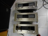
I am considering rebuilding a couple of Phase Linear 700B's and bridging them to drive a pair of large LF cabinets. One of the two wrecks pictured was revived and produced over 430 Watts per channel into an 8 ohm dummy load.
I have seen rebuilt PL700's produce 450 Watts. The 5 Amp rail fuses held and yet this calculates to 7.5 Amps through 8 ohms. Is this because fuses open due to heating and each rail fuse conducts for only have of each cycle?
These amplifiers are traditionally 'temperamental' but I would like to try some testing in bridge mode. My first assumption would be to verify output transistor current sharing before subjecting it to the higher current demands of bridging.
Question; Can anyone suggest a procedure for testing current sharing?
Thanks, Peter in Canada
Attachments
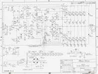
Not sure on topology w/o schematic. Usually parallel output stages will have emitter resistors for each output transistor to cause them to share equally. Input steady state signal like 1khz and measure the voltage drop across the resistors to see if it is equal to others of same type. Should be relatively close if sharing equally.
Thanks Freecrowder, I figured it would involve measuring the emitter resistor voltage under load. I have just discovered a Phase Linear service manual that describes driving the amplifier with a 200Hz sine wave to 53V output into 8 ohms, then reduce the line voltage to 75% to make emitter resistor measurements.
Unfortunately my variac does not have the capacity to power the amplifier under this kind of load..
Unfortunately my variac does not have the capacity to power the amplifier under this kind of load..
Attachments
Last edited:
Couple things about PL700s. They can be made reliable, but there are tricks to doing so.
1) If you're going to push them, you really need to put a cooling fan on them.
2) There's no peak limiting in these amps. It's worth coming up with some sort of solution for this.
3) Power the amps down before you connect / disconnect the inputs and speaker outputs.
Looking at the current state of your amps, my guess is that they saw PA use, either in an install or on the road. Since they've probably been abused, you'll want to make extra sure that they're in good working condition. A re-cap is a good idea at this point.