Vintage large speakers, I like their looks. 🙂
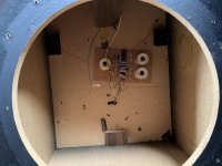
It does not really matter where you mount it or how. The location pictured is perfectly acceptable. What matters is that there are no steel screws near the coils. I would screw it down and keep the screws as far towards the corners of the board as possible.
It is worth checking the electrolytic capacitors for capacitance and loss or ESR. They might be out of spec. A cheap tester like the LCR-T4 or LCR-T7 (about $20) is not super accurate but will do. Desolder the crossover capacitors before measuring them. The tester can be calibrated with a low tolerance 100 nF MKS (or MKT or MKP) cap.
Last edited:
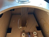
I use woodglue, and often with small woodblocks from leftover wood as standof to the piece of woodplate that contains the crossover is a bit elevated. And as long as it's not too close to any magnet or big metal piece (for the coils) it does not matter where the crossover is. 5cm (or 2" for those who think in imperial sizes) is a good safety distance for that from magnets, and half of that for other big metal pieces if there are any in the box.
And this tread should strictly seen be in the multiway section, where more people would react as this boxes are multiway boxes, not (single driver) fullrange section (which this is here)...
And this tread should strictly seen be in the multiway section, where more people would react as this boxes are multiway boxes, not (single driver) fullrange section (which this is here)...
Thx, I don;twish to create a duplicate thread if it will case any problems but only question would be can I put some wood glue anywhere on the bottom of the crossover and stick it exactly where it is?
I would make a kind of standof, so it's easier to remove it when needed for repair. But in pure technical terms, yes, you could. But i would not do it.
You could use double sided sticky foam pads if you don't wish to drill holes to take screws.
You may have to double them up thickness-wise to create the necessary clearance for the metal studs on the back of the board.
You may have to double them up thickness-wise to create the necessary clearance for the metal studs on the back of the board.
Last edited:
The metal 'studs' or terminals to which the crossover components are soldered will stick out of the back of the board, thus preventing the back of the board from making intimate contact with the rear of the enclosure....only question would be can I put some wood glue anywhere on the bottom of the crossover and stick it exactly where it is?
Simply applying glue will not give a a good bond. It may last for a time, but then fail - probably this is what happened in the first place.
That's why waxx's idea of using standoffs is such a good idea, and I have used the double sided pads to good effect in the past.
Last edited:
I'd let it rest on the bottom side of the enclosure and fix it with Uhu Tac (blue tac). Wires may need to be extended to be able to do that. Easily fixed, easily removed if you need to.
The metal 'studs' or terminals to which the crossover components are soldered will stick out of the back of the board, thus preventing the back of the board from making intimate contact with the rear of the enclosure.
Simply applying glue will not give a a good bond. It may last for a time, but then fail - probably this is what happened in the first place.
That's why waxx's idea of using standoffs is such a good idea, and I have used the double sided pads to good effect in the past.
Right, that is what I was taking that the back of the board should make direct contact with the wood of the cabinet. Sorry I don't know what a "standoff" is, any pics or links of it please?
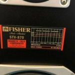
Also guys, these speakers shows 15-150 watts. The pair of 15" woofers needs to be refoamed and maybe the voice coil on one might need repair as it does not sound as good as the other.
So I am thinking might be simplest and even cheaper to replace the woofers. I am seeing the STV-870 model but that is showing 10-100 watts. I am not understanding why this later model [if it is a later model] would have a lower wattage?
Also is the "Input Power" of 15-150 watts rating of the 845 relating to the actual wattage of the 15" woofer in it so I would be downgrading if replacing with the 870 woofers showing 10-100 watts that is the wattage?
Attachments

Glue a couple of wood strips to the back of the crossover board (position them so as to avoid those 'studs').
Then apply glue to the back of the wood strips and attach the board to the enclosure wall via those strips.
The 'studs' will then stand clear of the enclosure wall - the wooden strips are acting as 'standoffs'.
It's harder to describe than to do!
Then apply glue to the back of the wood strips and attach the board to the enclosure wall via those strips.
The 'studs' will then stand clear of the enclosure wall - the wooden strips are acting as 'standoffs'.
It's harder to describe than to do!
Glue a couple of wood strips to the back of the crossover board (position them so as to avoid those 'studs').
Then apply glue to the back of the wood strips and attach the board to the enclosure wall via those strips.
The 'studs' will then stand clear of the enclosure wall - the wooden strips are acting as 'standoffs'.
It's harder to describe than to do!
I would never put a crossover inside an enclosure

No issues with power ratings in a domestic environment.Any idea on the power rating of the speakers issue please?
I'd say those woofers are gigantic for a domestic environment!
The STV-870 woofer is 12" so is not interchangeable with your 15" one.
ST -845
STV-870

ST -845
An externally hosted image should be here but it was not working when we last tested it.
STV-870
Fisher St-845
The only woofer that works on the st-845 is the original woofer, any other 15 inch Fisher wont work as intended.
The only woofer that works on the st-845 is the original woofer, any other 15 inch Fisher wont work as intended.
Fisher St-845
Crossover you can use wood glue you have to glue the crossover on the right side panel you can see the dirt from the previous glue used. I recommend trying to replace the surrounds do not replace the woofers just because the look similar the ST-845 carriers the largest magnet they ever used in the 80.s I have a pair and I tried several woofers from other 150 watts fisher and the sound is not the same. Make sure you brace the box thats a weak point too.
Good luck.
- Home
- Loudspeakers
- Multi-Way
- Where does the crossover go in Fisher ST-845?