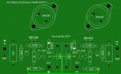
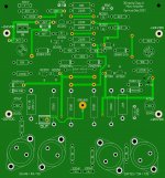
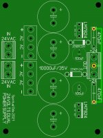
Has anyone built this amplifier? I have starting building this amp since november 2020 ( I have designed the original pcb with spint layout 6.0) adding an adjustable regulated power supply with 2N6284-2N6287 darlington transistors for 10A dc current plus 2 X 4 X 10.000uF capacitors at +-20V for the output & +-24 for the drivers.I have placed the pcbs on 2 huge heat sinks and i am ready for the final test. Your comments will be more than valiable!
Attachments
Hi
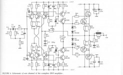
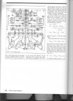
This is similar to an old Hafler amplifier like DH-200 but without drivers stages. You have the cascode VAS like in the DH-120. The open loop gain seems intentionally reduced but there still seem to need an output inductor filter for stability as it shows...
Increase the voltage and it is a typical class AB amplifier. I prefer CFA amplifier sound than VFA like this one. Although this one could also sound fine with bias in class A too.🙂
Normally a 20W class A amplifier requires more power supply.
R4 and R5 value could be reduced.
R21/22/23/24 values are higher than usually seen.
R25/26/27/28 are anormally high for a lateral mosfet and reduce class A power envelope.
C11/C12 is not something I have seen before....
Good luck
Fab
Last edited:
This project is very similar to elektor AXL class A amp. and comes from that era(1985) using 2 pairs of 2SJ48/49 and 2SK133/34 per channel. As far as the 68pF capacitor you are probably right. i tried to upload the original magazine pdf but it was too large, so I attach it pag by page.I hope it will be helpful. The quiescent current is high enough-2A- and the transistors are going to be very hot unless you use very big heat sinks!
Attachments

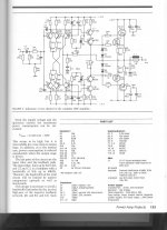

The output stage and the vertical mosfets design are the same as I used as per JLH,s mosfet amplifiers of the same era (1984) including the 1K gate stability resistors although John refined the value of them for the 2SJ48,s to a slightly lower value to help with the balance.
If your layout is very stable then you could even reduce the values a bit.
The BC550/560 are still good -low noise if you get the "B"/ "C" versions and high gain "C" version but can you get ---good ones nowadays ?
If your layout is very stable then you could even reduce the values a bit.
The BC550/560 are still good -low noise if you get the "B"/ "C" versions and high gain "C" version but can you get ---good ones nowadays ?
i built one many years ago, too.
it was nice - i modified a bit. major change was changing VAS stage to Hawksford cascode because I wanted to try it out.
🙂
still have the amp, but havent used it for years. i retired it after i built my Borbely Servo 50.
it was nice - i modified a bit. major change was changing VAS stage to Hawksford cascode because I wanted to try it out.
🙂
still have the amp, but havent used it for years. i retired it after i built my Borbely Servo 50.
The original TO3 mosfets he quotes in post #3 -2SK133/2SJ48 are vertical mosfets I know you are told nowadays to use Lateral as replacements but if you are saying the design is particular to lateral mosfets the output stage certainly isn't.
The output stage and the vertical mosfets design are the same as I used as per JLH,s mosfet amplifiers of the same era (1984) including the 1K gate stability resistors although John refined the value of them for the 2SJ48,s to a slightly lower value to help with the balance.
If your layout is very stable then you could even reduce the values a bit.
The BC550/560 are still good -low noise if you get the "B"/ "C" versions and high gain "C" version but can you get ---good ones nowadays ?
The 2SJ48/49/50 and their complementaries 2SK133/34/35 are identical each other except of the drain-source dc voltage(80-100-120). The BC550C - BC560C ordered from Mouser are of good quality and I easily match them (HFE mostly around 600). I am not going to use 2SJ48-2SK133 as per drawing because I have many 2SJ49-2SK134 in stock.
This is a lateral mosfet design not vertical.
Fab
Is it critical the mosfets matching and if they aren't, what it can be caused by that?
It doesn't take a lot to make mosfets oscillate but if you are worried about that the 1Kohm resistors in the gates do help .
If the design you are going to use is designed for the use of lateral mosfets then there are differences as it will be compensated for them but usually lateral mosfets require a bit more stability than V-mosfets as they came later than the V-mosfet types .
But it depends on the design --if you are worried read-
Mosfet | Types of MOSFET and their characteristics
The cascodes on the VASs should be referenced to each rail, not to 0V.
i.e. D3 and D4 are in the wrong place.
i.e. D3 and D4 are in the wrong place.
If you have matched output (between Same channel type) you definitely do not need the 0.22 ohms source resistors. If they are not so well matched then this source resistance may help to have a more equal current sharing. If badly matched then one of the two mosfet will heat more than the other.
This design would not be thermally stable with vertical mosfet.
Fab
This design would not be thermally stable with vertical mosfet.
Fab
Last edited:
I have noticed during my old AXL "renovation" that if the mosfets don't match each other, the quiescent current won't rise more than 780mA. If you don't match the BC550c and 560C there will be high offset voltage.
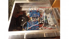
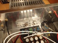
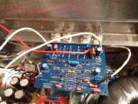
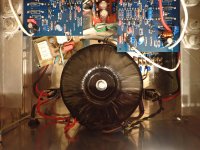
After quite a long time the amplifier is ready at last! Its sonic performance is amazing! So i would like to share with you who might be interested in building this fine class A amplifier some problems i have faced during the construction. The editor has recommended 2 transformers- power supplies and he was right because I had decided to build the amp with 1 transformer-2 secondaries 30V each 10A, 2 rectifing btidges and a common adjustable power supply for the output stage for the +-20VDC using 2 darlington transistors 2N6284 and 2N6287 for a pure 20VDC( The editor recommends just 40.000uF capacitors per channel without stabilization). The result was a huge heat sink at the back of the amp which gets really HOT hour after hour as there are about 8A per channel during operation. The quiescent current was set to 2A( you can measure 220mVdc across the 0.22R). The containing box is huge as well as the side heat sinks. The +-24VDC is common for both channels too!
Attachments


You probably can remove the cascode from VAS. It restricts the voltage swing and there is no real benefits.
Also I don’t like the compensation. It may rely on internal capacitance from the original parts to keep it stable. In another words, it may become unstable with other mosfets.
Also I don’t like the compensation. It may rely on internal capacitance from the original parts to keep it stable. In another words, it may become unstable with other mosfets.
Last edited:
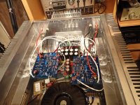
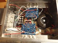
I have finally decided to build a dual-mono configuration with 2 power supplies- one per channel. I removed the power supply heat sink of the backside and placed the TO3 power supplies next to the heat sinks of the output mosfets.
Each channel has 1 transformer, 2 bridges, 2 filtering CRC boards of 40mF, one power supply for +/-24VDC and one for +/-20VDC( output mosfets). It is hot, quiet and huge but I can touch it for 10secs at least. It works perfectly with my 4R Cerwin Vega AT100. There are led indicators for all the voltages on the faceplate and 2 analog VU meters.
jxdking Thanks for your recommendation but I don't want to make any tweaking as this amp is a cheap and reliable construction. Besides, I didn't notice any mistakes while testing with my oscilloscope and signal generator at 1Khz-10Khz. Even the square pulses were satisfactory.
Unfortunately, my HP distortion analyzer is out of order and I couldn't measure the THD.
- Home
- Amplifiers
- Solid State
- LANG 20W class A amplifier