A lot of doubts?
26 Driver + Ale Moglia hybrid mu-follower
-26 can drives 307A?
-26 can drives 71A?
3A5 Driver + Ale Moglia hybrid mu-follower
-3A5 can drives 307A?
-3A5 can drives 71A?
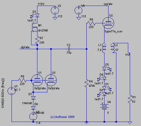
Iko DHT 3A5 headphone amp schematic:
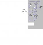
Ale Moglia DHT 3A5 preamp schematic:

Filament Bias: a practical example with 3A5 DHT – Bartola(R) Valves
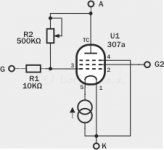
307A schade Ale Moglia info
307a DHT in triode and Schade feedback – Bartola(R) Valves
307a with schade feedback (Part II) – Bartola(R) Valves
Attached Iko 307A headphone amp output stage and Ale Moglia schade test for 307A because Ale said is the best way to use 307A but I don't know how to make the output stage with schade?
26 Driver + Ale Moglia hybrid mu-follower
-26 can drives 307A?
-26 can drives 71A?
3A5 Driver + Ale Moglia hybrid mu-follower
-3A5 can drives 307A?
-3A5 can drives 71A?
Iko DHT 3A5 headphone amp schematic:
Ale Moglia DHT 3A5 preamp schematic:
Filament Bias: a practical example with 3A5 DHT – Bartola(R) Valves
307A schade Ale Moglia info
307a DHT in triode and Schade feedback – Bartola(R) Valves
307a with schade feedback (Part II) – Bartola(R) Valves
Attached Iko 307A headphone amp output stage and Ale Moglia schade test for 307A because Ale said is the best way to use 307A but I don't know how to make the output stage with schade?
Attachments
Last edited:
Sennheiser HD600
Technical Specifications
Driver Type: Dynamic Driver.
Frequency Response: 12Hz – 40,500Hz.
THD 0.1%
Sensitivity: 97 dB SPL / 1V.
Impedance: 300 Ω
I no prefer Schade, Ale Moglia said in his blog is the best configuration for 307A.
Technical Specifications
Driver Type: Dynamic Driver.
Frequency Response: 12Hz – 40,500Hz.
THD 0.1%
Sensitivity: 97 dB SPL / 1V.
Impedance: 300 Ω
I no prefer Schade, Ale Moglia said in his blog is the best configuration for 307A.
Driving 300R is easy.
If you have 4:1 .. 5:1 (10k:600 .. 15k:600) transformer, any beefy driver tube capable driving it as parafeed.
If you have 4:1 .. 5:1 (10k:600 .. 15k:600) transformer, any beefy driver tube capable driving it as parafeed.
I have only on hand 307A, but Rod Coleman don't like it the distortion numbers.
Now I'm using 26 with Ale Moglia hybrid mu-follower measured output impedance 867,23 ohms so I connected 5:1 Edcor GXSE5 15k/600 & the sound is ok, 26 sees 7K5 with 6.8uF output capacitor the corner frequecy it's acceptable aprox. 31.21Hz if OPT can reach....
Now I'm using 26 with Ale Moglia hybrid mu-follower measured output impedance 867,23 ohms so I connected 5:1 Edcor GXSE5 15k/600 & the sound is ok, 26 sees 7K5 with 6.8uF output capacitor the corner frequecy it's acceptable aprox. 31.21Hz if OPT can reach....
Last edited:
307a is choosy tube.
Even in triode mode it's not enough linear, requiring 5k-6k5 transformer and with this load the distortion is not in the low side.
Even in triode mode it's not enough linear, requiring 5k-6k5 transformer and with this load the distortion is not in the low side.
Try to use 307a with active load (CCS or Ale type "gyrator") to minimise distortion, and load 15k:300 trafo as parafeed.
Member
Joined 2009
Paid Member
I’m thinking, with a 3a5 voltage amplifier and 307a as cathode follower driving a step down transformer, the distortion of the 307a is going to be low is it not?
Tried Ale Hybrid Mu-Follower with 26 and 15K:300 parafeed, sound is very very good.Try to use 307a with active load (CCS or Ale type "gyrator") to minimise distortion, and load 15k:300 trafo as parafeed.
Attached is the datasheet of the Western Electric 307A.
From page 3 (and page 6) it follows that a 307A will pass 39.9 mA at Va = Vg2 = 200 V, and Vg1 = -15 V.
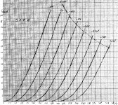
Now look at the curves of a triode connected 307A that I found on the internet some time ago. If you look at V(a+g2) = 200 V, and Vg1 = -15 V, you get I(a+g2) = 36.5 mA, which is close enough yo the 39.9 mA from the datasheet.
So assuming that these curves for the 307A in triode mode are close enough, the values in the schematic in post #10 can't be right. According to these curves, a triode connected 307A would only pass about 2 mA at Va = 262 V and Vg1 = -38V, while the schematic in post #10 shows 40 mA.
From page 3 (and page 6) it follows that a 307A will pass 39.9 mA at Va = Vg2 = 200 V, and Vg1 = -15 V.
Now look at the curves of a triode connected 307A that I found on the internet some time ago. If you look at V(a+g2) = 200 V, and Vg1 = -15 V, you get I(a+g2) = 36.5 mA, which is close enough yo the 39.9 mA from the datasheet.
So assuming that these curves for the 307A in triode mode are close enough, the values in the schematic in post #10 can't be right. According to these curves, a triode connected 307A would only pass about 2 mA at Va = 262 V and Vg1 = -38V, while the schematic in post #10 shows 40 mA.
Attachments

Looks like 4P1L or 2P29L are your easiest choices. Both possible in filament bias. What current in mA is your LL1660 gapped for? But have you considered a 2a3, if you can put some current through the LL1660? Or a 6B4G with Rod's regs?I have Chinese amorphous 15K-300R (150R+150R) also Lundhal LL1660 4.5-1 configured as OPT for 26
I have no idea who Iko is. But I think I do know where the wrong values in your schematic are coming from.I didn't designed the schematic (Iko designed). BTW as per data sheet you posted permissible operating conditions for Class A operation are included within the area, A B C D E, in figure 3.
The following curves were taken from this site: 307A - Bartola Valves
Accorcing to these curves, the values in your schematic would be spot on. But these curves can't be right unless the Western Electric datasheet for the 307A would be wrong. Like I wrote in post #12, the Western Electric datasheet shows I(a+g2) = 39.9 mA at Va = Vg2 = 200 V, and Vg1 = -15 V. But the curves from Bartola Valves show an I(a+g2) of around 90 mA at Va = Vg2 = 200 V, and Vg1 = -15 V.
For now I have no reason to believe that the Western Electric datasheet for the 307A is wrong.
I have Coleman regs. & tubes for 4P1L but having the 26 as preamp & reading the non favourable critics about SQ I finally forgot to make one.Looks like 4P1L or 2P29L are your easiest choices. Both possible in filament bias. What current in mA is your LL1660 gapped for? But have you considered a 2a3, if you can put some current through the LL1660? Or a 6B4G with Rod's regs?
Unfortunately mine LL1660 is 10mA gapped for 26 preamp I configured the LL1660 Alt Q 4.5 : 1 didn't liked the SQ also tried as choke following your advice & sounded better, but for 26 I'm using Ale Moglia Hybrid Mu-Followers - capacitor - Chinese amorphous 15K-300R (150R+150R) so parafeed and I like the sound a lot. I have also an Edcor GXSE5-15K - 5W, 15K Ohms - 600 Ohms single ended tube output transformer 100mA air gapped this one can be used for 4P1L or 307A.
Iko (diyAudio member) designed the 307A to use togheter 4P1L but after reading the SQ of 4P1L I let it go that route (attached schematic). I read your comments with interest about 2A3 / 6B4G / 6C4C / 6S4S tubes but I don't have any of these tubes on hand.
Maybe that Iko, being the designer, can comment on my posts #12 and #15?
To support my point:
For a 307A, being a pentode, and being measured under static conditions (meaning: all parameters, like Vg1, Vg2, and Va, stay fixed while measuring) it doesn't matter if at Va = Vg2 = 200 V, and Vg1 = -15 V the anode and the screen grid are connected to each other or not. As long as both are being fed with a stable 200 V, than the measured currents (Ia and Ig2) are identical for pentode and for triode mode.
For instance: Take a look in the attached Philips datasheet for the EL84 and compare the curves for pentode mode with Vg2 = 250 V and the curves for triode mode. In both you will find that at Va = Vg2 = 250 V, and Vg1 = -7.5 V I(a+Ig2) is about 53 mA. The same goes for Vg2 = 300 V. Iin both modes you will find that at Va = Vg2 = 300 V, and Vg1 = -12.5 V I(a + g2) = about 30 mA.
Check any other datasheet of pentodes with curves for pentode mode and triode mode, and compare the curves for a given Vg2 in pentode mode with the curves in triode mode at that given Vg2 (and Va = Vg2), with Vg1 also being the same in both cases. Ia+Ig2 will bethe same in both pentode and triode mode.
This is the reason why I'm sure that there something wrong with the curves for a triode connected 307A on the site of Bartola valves, unless the Western Electric datasheet for the 307A would be wrong. The difference between 39.9 mA (datasheet) and about 90 mA (curves Bartola Valves) is just way too big. And they can't be both true at the same time (unless the 307A tested by Bartola Valves was way out of specs or something like that).
Ofcourse there are big differences in the dynamical behaviour of a certain pentode, and that same pentode connected as a triode. But those differences don't matter under static conditions.
One of my personal 'breakthroughs' was the moment that I understood that "plate resistance" (= "internal resistance") is a dynamical parameter. It's not the same as the DC-resistance of a tube under static circumstances.
Attachments
Last edited:
A bias point based on the triode curves in post #12 could be:
The curves for a triode connected 307A I posted in post #12 probably came from the site of Pete Millett (but he also found them somewhere on the internet). See:
307A Push-Pull Amp
At the moment I'm involved in a conversation with Ale of Bartola Valves about his curves violating the Western Electric datasheet for the 307A. Ale still seems to think I'm wrong, but as far as I'm concerned the conversation is not finished yet. See in the comments:
307A - Conversation
I thought of the possibility that there are two different tube types that are both named 307A (note that the tube tested by Ale of Bartola Valves is a 307A/RK75 of Raytheon) but I haven't found evidence for that yet. As a by-product of that search I found out that the 4307-A by STC has the same specifications as the 307A by Western Electric. See attachment.
- Anode voltage = 283 V (being the voltage measured between anode and ground)
- Current = 40 mA
- Cathode voltage = 23 V (so the bias is - 23 V), which means the cathode resistor is 575 Ohm
The curves for a triode connected 307A I posted in post #12 probably came from the site of Pete Millett (but he also found them somewhere on the internet). See:
307A Push-Pull Amp
At the moment I'm involved in a conversation with Ale of Bartola Valves about his curves violating the Western Electric datasheet for the 307A. Ale still seems to think I'm wrong, but as far as I'm concerned the conversation is not finished yet. See in the comments:
307A - Conversation
I thought of the possibility that there are two different tube types that are both named 307A (note that the tube tested by Ale of Bartola Valves is a 307A/RK75 of Raytheon) but I haven't found evidence for that yet. As a by-product of that search I found out that the 4307-A by STC has the same specifications as the 307A by Western Electric. See attachment.
Attachments
- Home
- Amplifiers
- Tubes / Valves
- DHT headphone amp