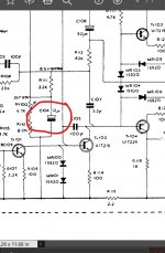
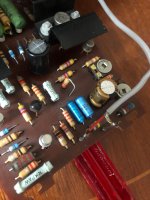
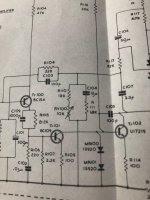
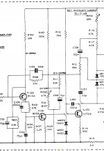
First post here! Have been lurking around here for over three years, but never registered. Last weekend I bought a really nice early Quad 303 along with an early Quad 33 unit. Both have serial numbers #11xx. I have been recapping both during the last couple of days. I tuned the rail voltage as well as quiescent current last night and fired the 303 up. Left channel is working flawlessly but the right one is noisy with volume set to zero. I thought the first order of business was to order replacement resistors for the larger carbon composite ones, which usually go bad. I thought of 0.5w metal film resistors. Would that be appropriate? As I've understood it this version has the first boards, and it's hard to find any info on these on the web. Thankfully it included schematic for the 303, which seems impossible to find online. I'm gonna make a scan of it later on if somebody might need it as well. My second question is, C104 is a bipolar electrolytic (I assume?) capacitor on this version on the driver boards. Is it okay to change it with a polarized capacitor instead as in the later versions of the boards? See pictures. Thankful for any input!
Last edited:
C104 (12uF?) would be an electrolytic, not bi-polar. It sees around 8 volts DC across it in normal conditions of use.
Try attaching your images to the forum 🙂
How to attach images to your posts.
Try attaching your images to the forum 🙂
How to attach images to your posts.
Attachments
Please re-post the photos as attachments.
They will then stay rather that disappear.
I'm sure many people will want to subscribe to this thread.
Pictures -- Why Not attach Them ??
They will then stay rather that disappear.
I'm sure many people will want to subscribe to this thread.
Pictures -- Why Not attach Them ??
Thanks Alan! Didn't see that you could attach images, and seemed to have messed up the link a bit. Couldn't edit them in, since 30 minutes had gone. As you can see from the schematic (the photo) it has a bipolar capacitor, is it not?
C104 doesn't need to be bipolar, if the schematic is correct. It is ground referenced and the schematic clearly says the plus end is 8.5 v above ground. The black ends of it & C106 C101 C16 are the negative ends. Note also the electrolytic C100, which these days for .68 uf should be replaced with film or even CGO ceramic. The least distorting film John Curl said is polyprophylene. The most commonly stocked film is mylar. You may have trouble getting film small enough, distributors tend to not stock voltages under 63.
Those carbon comp resistors are the cheap european ones. So yes they could have been damaged by moisture. However, this should show up as lower resistance, so measure them instead of potentially damaging the board by replacing them all. Resistances under 100k usually do not have enough hiss to be worth replacing with metal film. Watch out new vishay metal film are tiny, meant to operate at hundreds of degrees temp at rated wattage. Your board cannot stand that temp. Use >300 v rated resistors to get something long enough to run cool enough.
These early transistors and diodes can also potentially be the source of noise, particularly popcorn noise. There was a lot of human skin & hair floating around fab rooms in the seventies. If you have a scope, probing around from front to back with the input shorted could help pinpoint the area causing the noise. If not building a 100* gain op amp circuit, followed by a 2 vac or even 20 vac analog voltmeter, may be cheaper. Cheap DVM make up random numbers on AC scale for frequencies other than 50 or 60 hz. RMS DVM cost too much to entirely miss frequencies in excess of 7 khz. Which they do.
Safety warning to new repairmen. 24 V across the heart can stop it. Use only one hand probing an amp with power on. Put the negative of the meter to ground with an alligator clip, with the same hand you probe with. Don't wear rings or jewelry on hands wrists or neck. 1 v @ 30 A through a ring can burn your flesh to charcoal. Wear safety glasses, parts can explode and solder splashes, especially desoldering.
Happy hunting.
Last edited:
Most DVMs AC scale is designed for all common mains frequencies which includes 400Hz, so you should be able to rely on it for test tones in the 50 to 400Hz range, and usually well beyond. 400Hz is used on small systems like boats and planes, so the generators/motors/transformers can be smaller.
There are no bipolar capacitors in a 303. For the noise I would replace Tr100, the input transistor. Use BC560. Don't change the biasing diodes!
Thanks for all the replies and suggestions!
Finally had time to work a bit more on this 303. Replaced C100 with 1uF Wima film capacitor, C104 with 22uF Nichicon Gold. Removed the TR100 BC154 and replaced it with BC560C, the noise was lowered a bit but not removed. Removed the four carbon composites resistors on the board, R100 R110 R107 and R115, replaed them with metal film resistors. Noise is now gone! Feels great.
Finally had time to work a bit more on this 303. Replaced C100 with 1uF Wima film capacitor, C104 with 22uF Nichicon Gold. Removed the TR100 BC154 and replaced it with BC560C, the noise was lowered a bit but not removed. Removed the four carbon composites resistors on the board, R100 R110 R107 and R115, replaed them with metal film resistors. Noise is now gone! Feels great.
Congratulations!
Some parts have gotten better over the years. Better engineering, better quality control.
Some parts have gotten better over the years. Better engineering, better quality control.
Any experiences with the upgrade described here ?
Quad 303 modification
Quad 303 circuit diagram - large copy
Quad 303 modification
Quad 303 circuit diagram - large copy
If the point of that as stated is to increase bias stability, there is no problem to solve. I last biased mine fifteen years ago and on checking it is still exactly the same. I've biased hundreds of these.
- Home
- Amplifiers
- Solid State
- Early Quad 303 refurbishing