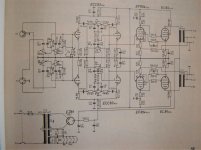
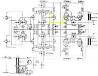
I have come across this old German amp on an auction site, a RIM Stereomaster, and there was a schematic with the listing which has stretched my understanding of tube circuits.
The amplifier is EL84 single ended output, with an EF804 driver and ECC83 input stage + tone controls. However I am finding it hard to understand the output stage.
There is negative feedback from the 4ohm tap on the output transformer.
The EL84 is DC coupled to the EF804. The EF804 has a capacitor to ground and some potential divider arrangement on its load resistor. The screen of the EF804 is coupled to the cathode of the EL84.
It is not completely obvious how the EF804 is getting its input, or how the feedback circuits work together.
Would be very interesting if someone could explain how the driver is functioning.
Attachments
Last edited:
There a mistake in the schematic: R13 (on top of the EQ) is bypassed.
The configuration on top of the EF804 is similar to a Marshall amp configuration (in that case the plate load is switchable to have different distortion figures).
Due to the fact the tube has really low currents below 1 mA ( https://frank.pocnet.net/sheets/128/e/EF804S.pdf ), can it be that the 100 nF is there as a power supply cap? Together with the dropping resistor of 820k gives a cutoff frequency of 2 Hz.
R37 and R37 is sort of cathode feedback to the output tubes whilst R35 and R36 are a feedback from cathode of the EL84 to g2 of EF804 (I saw something similar in some input stage for old studio mixers).
I can be wrong, but this is how I would interpret that schematic.
An interesting design, maximizing the use of a single ef804 to spare a tube. Note the plate resistor 2.2M , DC coupled with screen stabilizing the DC bias.
A scholar example of most of the tricks that could be done to minimize number of tubes, still with impressing distortion figures due to heavy NFB.
A scholar example of most of the tricks that could be done to minimize number of tubes, still with impressing distortion figures due to heavy NFB.
An interesting design, maximizing the use of a single ef804 to spare a tube. Note the plate resistor 2.2M , DC coupled with screen stabilizing the DC bias.
A scholar example of most of the tricks that could be done to minimize number of tubes, still with impressing distortion figures due to heavy NFB.
Yes, a beautiful design but strange to modern eyes. Starved current operation is so device dependent, and so weird looking that DIYers never even try it today. The DC feedback to stabilize it is very elegant. Great to see real Baxandall tone controls too.
YOS,
Chris
Have a look at the Mullard 3-3 amplifier. Mullard 3-3. Three Watt Amplifier You will see the similarities straight away.
If you read the 'Circuit Description' it outlines the operation and AC and DC conditions. The EF804 is essentially the same as an EF86.
There are more detailed explanations if you search Mullard 3-3.
If you read the 'Circuit Description' it outlines the operation and AC and DC conditions. The EF804 is essentially the same as an EF86.
There are more detailed explanations if you search Mullard 3-3.
I guess that's the definition of a classic. You can forget about it for half a century or more, but when you see it again, it's still beautiful.
Thanks guys,
Chris
Thanks guys,
Chris
- Home
- Amplifiers
- Tubes / Valves
- RIM Stereomaster