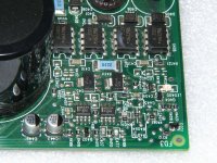
I have a nice mtx 92001 that came in and there are two sections of the board with visible damage. Unfortunately there are significant amount of SMD components missing and/or obliterated.
I was hoping someone would have a picture of these sections of the board they might be able to share.
Thank you in advance
And
I was hoping someone would have a picture of these sections of the board they might be able to share.
Thank you in advance
An externally hosted image should be here but it was not working when we last tested it.
And
An externally hosted image should be here but it was not working when we last tested it.
MTX have a lot of "missing" components on their boards, do not worry as nothing is missing or obliterated it just simply isn't used in that application. I thought that too when I got my first MTX.
If you have Perry's repair tutorial (If you do not, GET IT) remember/FYI there is a folder on just MTX and many photos that are extremely handy to reference (probably just like the one he posted above)
If you have Perry's repair tutorial (If you do not, GET IT) remember/FYI there is a folder on just MTX and many photos that are extremely handy to reference (probably just like the one he posted above)
Well I finally got around to diving into this amp for some fun. Lotsnof blown components. Removed all 30N50 output fets. PS has 4 80NF55s just to get it running. Power supply is up and running, builds rails properly (+/-100v), generates +15v and -15v vcc for all op amps. When driven with 40hz into the RCAs I even have a nice 40hz square wave coming out of the NE5532s to the toasty optocouplers (all 4 toasty optocouplers are still in circuit.)
FET 401 was shorted so I replaced it with a known good 42N20. Oddly enough I'm not getting any rail voltage on any pins of that fet.
My other issue is that voltage from pin 5 to 8 on all 4 optocouplers should be around 20v above negative rail. It is not even close. (0v difference between 5 and 8 and those pins show ~22v DC reference to main ground.)
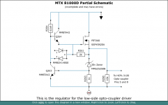
I see parts of a voltage regulation circuit around FET 401, but can't find half of it and was wondering were the rest of the components are?
FET 401 was shorted so I replaced it with a known good 42N20. Oddly enough I'm not getting any rail voltage on any pins of that fet.
My other issue is that voltage from pin 5 to 8 on all 4 optocouplers should be around 20v above negative rail. It is not even close. (0v difference between 5 and 8 and those pins show ~22v DC reference to main ground.)
I see parts of a voltage regulation circuit around FET 401, but can't find half of it and was wondering were the rest of the components are?
Last edited:
The rest of the FET401 regulator components may be near opto-coupler U407.
If you remove the opto-couplers and want to power the amp up (with output FETs in the circuit), you must install a jumper between pins 5 and 6/7 to prevent the FETs from switching on.
On the edge of the amp near the 5532s, there are 4 large rail caps. Between the center two, is there a resistor buried in silicone?
That resistor sometimes opens and sometimes has bad solder connections. It's in parallel with the missing SMD resistor pads so you may be able to check it there.
Yup loose and the resistor is reading 9170 ohms out of circuit. I am color blind to brown, green, blue, purple, orange, and red so I have a heck of a time reading color
 bands.
My best guess is this is a 10.9ohm resistor?
My best guess is this is a 10.9ohm resistor?
(Optocouplers now out of circuit.) fixed the loose resistor issue and now I'm getting 15.5 to 16.5v (it varies randomly) across pins 5 and 8 on octocouplers U407 and U403. The other two (u406 and u402) have full negative rail on pin 5 and roughly ground on pin 8
Still no rail voltage of any kind on any legs of Fet401. Why is that?
Still no rail voltage of any kind on any legs of Fet401. Why is that?
I gotcha. Hey quick couple of questions. D404 appears to be a 15v zener. I have none of those. I do have a 20v zener as listed in that 81000d schematic. Can I substitute it in? I'm guessing it would make the voltage differential at pins 5 to 8 go a touch higher than on the high side?
Here's what I've cross referenced so far. Do you see anything that appears incorrect?
D400 = MMBD4148A (diode array pictured is "SE")
D404 = MMBSZ-5245B (15v) (20v zener pictured)
Q403 = MMBTA42 (Q264)
Q401 = MMBTA42 (Q263)
FET401 = FET260 (45N20/42N20)
R4021 = R260
R4010 = R263
R4007 = R261
R4003 = R264
If that's all correct it may help others that come across this thread.
Thank you Perry!!!
Ok I double checked everything first and in this instance leg 2 of the D400 isn't used so for this case only 4148se is interchangeable with 4148a, and the 20v zener worked great!!
I now have 20v across the needed pins!!
Thank you again!!!
I now have 20v across the needed pins!!
Thank you again!!!
The semiconductors appear to be correct.
The 15v Zener may take some the load off of the optocouplers but may be OK.
From photos,
R4010 is 1k marked 1001
R4003 61.9k 6192
R4007 10k 1002
R4021 10k 1002
The 15v Zener may take some the load off of the optocouplers but may be OK.
From photos,
R4010 is 1k marked 1001
R4003 61.9k 6192
R4007 10k 1002
R4021 10k 1002
Last edited:
One more question now related to parts substitution.
The 80NF55s apparently are obsolete. It looks like 47NF08s are close with the exception of Ciss. The obsolete was 4400 vs the 6600. Thoughts?
Here's the two spec sheets.
047AN08

And the 80NF55

The 80NF55s apparently are obsolete. It looks like 47NF08s are close with the exception of Ciss. The obsolete was 4400 vs the 6600. Thoughts?
Here's the two spec sheets.
047AN08
And the 80NF55
The drive circuit for these amps is pretty tolerant and you could likely use the FDH047AN08 but they will be a tougher load than the originals. I used the IRF3205 in the TO-220 amps. The IRFP064N (the same case style you have) is about the same FET.
Oh nice thank you I do have those handy!!
If memory serves me mtx amps need feedback to oscillate? Could I just run 1 30N20 in each output bank to fire it up?
If memory serves me mtx amps need feedback to oscillate? Could I just run 1 30N20 in each output bank to fire it up?
- Home
- General Interest
- Car Audio
- MTX 92001 pictures of components?