Trouble for the newbie of all newbies:
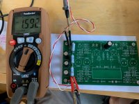
I am at the point in the build where I am checking the voltage in the power supply portion of the board. It is supposed to be 24 volts, of course, and over and over I get .57. My meter shows this whether the power switch is on or off.
Here are the pics:


Ok. I am all ears, and grateful for whatever help I can get.
Bonesthrower
Lincoln, Nebraska
I am at the point in the build where I am checking the voltage in the power supply portion of the board. It is supposed to be 24 volts, of course, and over and over I get .57. My meter shows this whether the power switch is on or off.
Here are the pics:
Ok. I am all ears, and grateful for whatever help I can get.
Bonesthrower
Lincoln, Nebraska
T4 connection place on the pcb are not for resistor but zener diode 🙂 Have a nice day
B1 with Korg Nutube - diyAudio Guides
B1 with Korg Nutube - diyAudio Guides
^ +1
Bonesthrower - You may know about this, but just in case. It has exceptional photos and shows what parts to stuff for each step.
B1 with Korg Nutube - diyAudio Guides
Happy Building!
Edited to Add - LOL! Soundhappy linked to the same guide. Well, it is a good one.
Bonesthrower - You may know about this, but just in case. It has exceptional photos and shows what parts to stuff for each step.
B1 with Korg Nutube - diyAudio Guides
Happy Building!
Edited to Add - LOL! Soundhappy linked to the same guide. Well, it is a good one.
Last edited:
Google what is electronic continuity test
Edit: for example What is Continuity and How to Test for it With a Multimeter - YouTube
and one more useful thing is a clean all flux residues for circuit reliability
How To Clean Printed Circuit Boards - YouTube 🙂 Have fun is a great hobby
Edit: for example What is Continuity and How to Test for it With a Multimeter - YouTube
and one more useful thing is a clean all flux residues for circuit reliability
How To Clean Printed Circuit Boards - YouTube 🙂 Have fun is a great hobby
T4 connection place on the pcb are not for resistor but zener diode 🙂 Have a nice day
B1 with Korg Nutube - diyAudio Guides
DOH!
Thanks for the feedback fellas. I am using the guide. Not sure how I made that mistake.
Bonesthrower
Lincoln, Nebraska
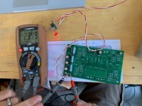
Ok. So I put the diode in. I am still not getting 24V. Here is what I see:
I ran a continuity test before hooking up the wires from the board to the power jack. There was good continuity at least there.
I then hooked up the power jack and put the power to it. When I put the switch on, the LED lights. Checking the voltage still gets me 0.000. When I pull one of the alligator clips off, I get 13. volts on the meter. When I put it back on and pull the other one off, I get 14 volts also. I don't understand enough to know why, but that seemed significant.
Any suggestions?
Bones
Did you order everything from the store? Full kit?
Time for pics again and showing exactly where you are in your build, how you have your switch wired, how you have your DMM set, and where you have your probes when you measure. You can't measure a voltage with one of the probes disconnected if you're doing it like in the guide. 😉
Edited to add - You can't measure the intended voltage at all with only one probe connected to the circuit, regardless of the guide, but I thought that might sound snarky. I think pics are important to show how you got a voltage with only one probe connected (unless I misread).
Last edited:
@ Bones
Zener diode polarisation on the board are in the right direction ?
COM(black) probe connected to the pcb ground
RED probe step by step
to T1 point : how much volts ?
then T2, T3 and T4 ?
Zener diode polarisation on the board are in the right direction ?
COM(black) probe connected to the pcb ground
RED probe step by step
to T1 point : how much volts ?
then T2, T3 and T4 ?
Ok. So I put the diode in. I am still not getting 24V. Here is what I see:
I ran a continuity test before hooking up the wires from the board to the power jack. There was good continuity at least there.
I then hooked up the power jack and put the power to it. When I put the switch on, the LED lights. Checking the voltage still gets me 0.000. When I pull one of the alligator clips off, I get 13. volts on the meter. When I put it back on and pull the other one off, I get 14 volts also. I don't understand enough to know why, but that seemed significant.
Any suggestions?
Bones
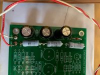
From the picture in your first post, you have one of the electrolytic caps in that isn't part of the PS test that 6L6's build guide shows. take a look at this picture from his guide.
Attachments
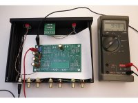
Back to the newbie feels stupid troubleshoot. Here are my initial pics and multimeter readings.
When switch is on, LED is on.
A couple other things I noticed:
For each of the tests with the MM, the V reading stayed the same when the switch was off. When I switched it on, the reading slowly reduced. When I flipped the switch off again, it stopped at the spot it was at when I switched it.
Soundhappy -- I don't know exactly what you mean when you say put the red probe "to T1", "to T2" etc. Does it matter where on that transistor, etc. Let me know and I will do pics of each of those connections and readings.
Folks- I am not a total idiot, but I am very inexperienced. Please tell me exactly what you see and I will grin and bear it. I have more will than ability or knowledge at this point.
And thank you for whatever help you are able to provide.
Bones
Attachments
-
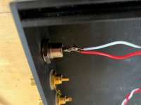 9 - barrel connections.jpg51.8 KB · Views: 58
 -
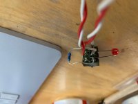 8 - switch wiring.jpg54.8 KB · Views: 64
 -
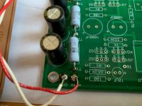
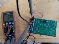 No 7 - 9.5 V test per the build guide - switch is off.jpg90.8 KB · Views: 66
 -
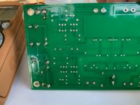 6 -- back of board solders.jpg65.7 KB · Views: 61
 -
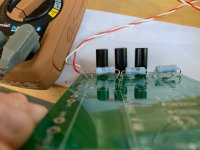 No 5 -- side shot of transistors .jpg63.4 KB · Views: 63
 -
 No 4 -- transistor solder, etc.jpg76.5 KB · Views: 109
 -
 No 3 - connections to power and ground.jpg79.7 KB · Views: 120
 -
 2 - switch is on.jpg89.8 KB · Views: 115
 -
 1 - switch is off.jpg91.3 KB · Views: 123
Bones,
I see areas of cold soldered joints. The board needs resoldering. Best to desolder using solder wick and try again. Watch some soldering videos on you tube.
You must prove first that +24V DC is coming into the PCB board. Or else, all else is lost.
Perhaps remove the switch from the equation so you can establish 24V DC first. Direct connection that is.
Best,
Anand.
Last edited:
Well, not sure what I did, but when I took off the alligator clips and just used the probes, I am showing 24.1 V on the 24 V test, and 9.1 on the 9V test.
DISCO.
Thanks for the feedback everyone. I am sure I will be back for more.
Bones
DISCO.
Thanks for the feedback everyone. I am sure I will be back for more.
Bones
Bones,
That's great but it's not really a DISCO, yet. You established that you may still have cold solder joints. I imagine that the small bit of pressure you used when placing the DMM pins directly on the +24/GND connection sites allowed for continuity so presto, your voltage was +24V as it should be.
I would still desolder with solder wick, use flux to enhance thorough removal and then resolder so that the solder flows smoothly and you do not have lumps/blobs of solder. It should be smooth and shiny. The temperature of the iron tip has to be within range as well.
I use a Hakko 599B Soldering tip cleaner, GC Electronics Liquid Solder flux, Chemtronics ES1696 No Clean Plus liquid solder flux remover, and KimWipes to wipe off the excess and get a clean finish.
EEVblog #180 - Soldering Tutorial Part 1 - Tools - YouTube
If you don't address the issue, the joint will fail again, maybe today, tomorrow or next year. You want joint permanency and reliability.
Alternatively, your alligator clips may have not had good continuity and your DMM couldn't pick up the voltage. Only you can know that...it would be hard to tell from here.
Good luck,
Anand.
Last edited:
- Home
- Amplifiers
- Pass Labs
- Newbie Troubleshoot: Korg Nutube Pre-Amp