I've had trouble finding mosfets that are properly matched for use in my F5 Turbo V3 monoblocks. I bought several sets from reputable sellers, but I don't believe that they were matched under the conditions in which I am using them. This has caused me to blow a few sets of outputs when biasing the amp to a level where the heat sinks to approach 50C. I believe that the high bias on an unmatched, current-hogging mosfet has caused one or more of the diodes to conduct and led to smoke.
I am considering removing the diodes altogether, as some have suggested, but thought I would first try matching my own set of mosfets first under real world conditions.
I've read many of the various mosfet matching threads, but I haven't found an answer to the basic question of how to simulate the real world conditions of the mosfets in my F5 Turbo.
I intend to use the basic technique set forth by Nelson Pass in the following article, which many others have used:
https://www.firstwatt.com/pdf/art_matching.pdf
But my F5 Turbos have 41V rails, so I have the following questions:
1) Should I use a 40V power supply when testing the mosfets? Or is 15V enough?
2) How much current should I aim for with the I=(V-4)/R1 formula set forth in the article?
3) How many watts does R1 need to be rated for if the voltage is increased to 40V?
4) I plan to test the mosfets while they are screwed to the heatsink. How long should I let them heat up before taking the reading? Should I let them completely stabilize, which could take a while?
5) How closely should they be matched? I've seen 30mv, 10mv, etc.
I would really appreciate some help on this.
Thanks
1. no need for 40V
2. best to match them at current in which they're going to work in circuit
3.P=I^2 x R ; that's dissipation ; you must use 3 times stronger part
4. you'll see when numbers goes steady
5. say that, considering that F5T is source resistors , 50mV is nice while still practical bracket
for this test, best to use variable DC source, so you can choose some standard resistor value then compute adequate DC for test
be it lab supply, or {variac - Donut- rectifier- filter}
Food for thought...
If you assume matching under different conditions to your desired operating conditions to be the culprit; under what conditions would you want to match to ensure success? Are you concerned re: how the parts behave relative to each other at startup or steady-state? Both?
Did you ask under which conditions previous parts were matched? It would be a shame to repeat their processes to test your theory and create more smoke. If your suppliers used different processes, you now have even more data for conditions to consider and potentially avoid. If any of them had done it exactly the way you'd consider doing it yourself; you may reconsider your theory, your matching process, or both.
I hear the F5T (particularly the V3) can be a fickle mistress. Hope she tickles your fancy soon enough.
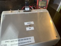
When I match I'm doing some decent size batches. I made a jig that uses a regulated power supply and has a switch to use 2 different resistors for current setting. I'm doing IRFP240's and 9240's at 170mA. I have a switch that puts power to the device, and starts a timer. When the time is done I get a relay click and LED coming on. I'm watching the voltage when the click/LED happens. Then I turn it off, write the voltage on the device, then repeat.
When the measuring is done, then I sort them all in order. So they're not matched in operating condition, but they're matched relative to the batch. And all in consistent conditions (temp, power, time). With a big batch you can get very close matches.
I've played with changing the current and doing 2nd round of spot checking matches at the alternate current, and they track well.
I did a full set of IRF9610's recently at higher and lower current, and they tracked well.
If you're going go for "actual conditions", you'll want the heat sink to be a consistent temp for each one.
How long is the amp running before something blows up? Seconds? Minutes? Hours? Days?
Have you measured the current of each Mosfet in the F5 V3 Turbo when it's operating? How close are they running while in the amp? I checked that on the V3 Turbo's I built for a friend just to be sure.
I have a Rawson Aleph 5 I'll be rebuilding and I'm convinced the mosfets are absolutely unmatched based on the currents I measured. I'm replacing the whole set, but I'll pull the old ones and measure them just to see how far off they are...
Pic is from last batch results.
Attachments

Randy, how do I get me one of those PRO Gold Signature Reference Editions?! 😀 😀 😀
That is seriously the coolest matching "jig" I've ever seen.
That is seriously the coolest matching "jig" I've ever seen.
When I match I'm doing some decent size batches. I made a jig that uses a regulated power supply and has a switch to use 2 different resistors for current setting. I'm doing IRFP240's and 9240's at 170mA. I have a switch that puts power to the device, and starts a timer. When the time is done I get a relay click and LED coming on. I'm watching the voltage when the click/LED happens. Then I turn it off, write the voltage on the device, then repeat.
When the measuring is done, then I sort them all in order. So they're not matched in operating condition, but they're matched relative to the batch. And all in consistent conditions (temp, power, time). With a big batch you can get very close matches.
I've played with changing the current and doing 2nd round of spot checking matches at the alternate current, and they track well.
I did a full set of IRF9610's recently at higher and lower current, and they tracked well.
If you're going go for "actual conditions", you'll want the heat sink to be a consistent temp for each one.
I am going to try strapping some to my big heat sinks, using the Nelson Pass model, letting them warm up for a while, and then seeing how they measure. I have a "matched" set from another seller that I am going to test first to see if they diverge. I'll report back in a few days.
How long is the amp running before something blows up? Seconds? Minutes? Hours? Days?
Have you measured the current of each Mosfet in the F5 V3 Turbo when it's operating? How close are they running while in the amp? I checked that on the V3 Turbo's I built for a friend just to be sure.
I have a Rawson Aleph 5 I'll be rebuilding and I'm convinced the mosfets are absolutely unmatched based on the currents I measured. I'm replacing the whole set, but I'll pull the old ones and measure them just to see how far off they are...
Pic is from last batch results.
Rhthatcher,
I measured the voltage drop across the four source resistors (which are .5% tolerance) on one side of the problematic monoblock (other monoblock is working fine) and there was a deviation of up to 150mv or so. When I biased the highest measuring one at around 350mv, the lowest measuring one would be around 200mv, which was a big deviation.
I used the amp like that for a while, monitoring it closely for 3 or 4 days. Heat sinks we getting up to about 47C. Stopped monitoring after that and within a week, poof! Amp was not too hot when it happened. I estimate around 47C. I don't know how high the bias had drifted, but I suspect over 400mv.
On your rig, how long is the timer? What is the voltage? I'm assuming the mosfets are not getting too hot because you don't appear to be using a heat sink.
I'm worried that the mosfets might measure similar under those conditions, but diverge significantly when the temp gets much higher.
Not sure how to address this issue, but it seams to be a legitimate problem with many "matched" mosfets.
I myself have tried matching Vgs with an Atlas DCA55, but mosfets that appear perfectly matched at room temperature, quickly diverge in real world use.
I measured the voltage drop across the four source resistors (which are .5% tolerance) on one side of the problematic monoblock (other monoblock is working fine) and there was a deviation of up to 150mv or so. When I biased the highest measuring one at around 350mv, the lowest measuring one would be around 200mv, which was a big deviation.
That seems like a very big deviation. How many sets of Mosfets have released the magic smoke? If it's more than one, there might be more going on with the amp.
12V regulated supply, resistor to get 170mA, and it's around 12-15 seconds. I forget the exact setpoint. It was the twist of a trimpot and and done.On your rig, how long is the timer? What is the voltage? I'm assuming the mosfets are not getting too hot because you don't appear to be using a heat sink.
The Mosfets don't get hot. They fire up and drift slowly. My first batch I left on the matcher (old Rev 1 matcher - not the gold signature reference edition 😀 ) for 45 seconds timing with an iPhone stopwatch. Vgs drifts pretty slow, so measuring at 15 seconds vs. 30 or 45 will capture a snapshot in time. from that standpoint, consistency is key.
I myself have tried matching Vgs with an Atlas DCA55, but mosfets that appear perfectly matched at room temperature, quickly diverge in real world use.
I can't say I'm familiar with that one and how well it works for this test..
That seems like a very big deviation. How many sets of Mosfets have released the magic smoke? If it's more than one, there might be more going on with the amp.
I ruined two sets with a different problem that Audiosan helped me identify. I had two thermistors installed on each of the N and P channels, instead of one, which screwed things up. But I had problems with them being matched as well.
After I fixed that, the one amp works fine and the mosfets are all within a reasonable range. On the other amp, it worked, but there was a substantial difference, and it eventually melted down.
I'm pretty confident that the problem is the mosfets because everything sounded great and worked fine. Stable bias, stable offset. I tested the other parts previously and found no issues. I even replaced the source resistors with .5% tolerate instead of 1% tolerance.
From looking at the schematic, it seems like any imbalance would have to be caused by unmatched mosfets or unmatched resistors, but let me know if others are aware of other potential causes.
Do you recall which mosfet(s) went poof, and how their source resistor voltages
measured?
I haven't taken it apart yet to check. Waiting for power supply to arrive for my mosfet testing this weekend. I'll let you know, but if one goes, I think others often follow.
So I'm using the Pass Labs method, with a 15V power supply and 2 100hm resistors in parallel, which should generate a current of about 220mv.
I have the transistor on a large heat sink, but while the resistors get warm, the transistor does not seem to heat up at all.
The good news is that the "matched" set that I have does appear to measure even, but I am still concerned that this is not going to hold up at higher temps and voltages.
Any suggestions on how to do a more real world test?
I'm following the schematic in the following article:
https://www.firstwatt.com/pdf/art_matching.pdf
It works, as my "matched" set are measuring between 4.00 and 4.02 Vgs, but they are not heating up or heating up the heat sink.
I am using a 15V DC power supply and two 100 ohm 3 watt resistors in parallel, set up as in the schematic.
https://www.firstwatt.com/pdf/art_matching.pdf
It works, as my "matched" set are measuring between 4.00 and 4.02 Vgs, but they are not heating up or heating up the heat sink.
I am using a 15V DC power supply and two 100 ohm 3 watt resistors in parallel, set up as in the schematic.
you have 4V(ish) across mosfet, rest across 50R
current is (15-4)V/50R=220mA
dissipation is U x I, so 880mW across mosfet (practically nothing) and 2W2 across resistors
everything as prescribed
current is (15-4)V/50R=220mA
dissipation is U x I, so 880mW across mosfet (practically nothing) and 2W2 across resistors
everything as prescribed
I know it is set up correctly and working, but this approach doesn't seem like it will replicate the Mosfets performance at higher temps.
I recall numerous people posting about the importance of using a heat sink when testing mosfets, but I doubt it matters with this setup. The mosfet doesn't even get warm.
I'm trying to understand if there is a way to measure Vgs at a higher temperature.
I recall numerous people posting about the importance of using a heat sink when testing mosfets, but I doubt it matters with this setup. The mosfet doesn't even get warm.
I'm trying to understand if there is a way to measure Vgs at a higher temperature.
no need for that - you're not chasing actual data in working am(p)bient, you're matching them
it's well known and confirmed that properly matched ( meaning - all in controlled conditions) mosfets are tracking well in tougher and hotter circumstances
without heatsink, even 880mW would show you as much longer time needed for equilibrium, pulling harder at TempCo intrinsic mechanismus
it's well known and confirmed that properly matched ( meaning - all in controlled conditions) mosfets are tracking well in tougher and hotter circumstances
without heatsink, even 880mW would show you as much longer time needed for equilibrium, pulling harder at TempCo intrinsic mechanismus
- Home
- Amplifiers
- Pass Labs
- Mosfet Matching for F5T V3 - Correct Voltage/Heatsinking/Resistor