Hi!
My name is Andi and i am new to this great forum!
I started a new hobby trying to repair my rockford amp and i need some help 🙁
I have a broken punch 225X2 on my table and i am out of ideas what to check next.
The backplate says 225.2 and the mainboard has 225X2 printed below the transformer, the big Capacitors are from 1998.
The board prints: PC-1885-A
Now it has clean audio but i still have problems with one output FET which gets hot after a short time.
I love spending time on that thing for learning and i stopped counting hours 😀
I have no schematic , i just tried to find faulty components.
Now i am at a point where i need to be kicked to the right direction and hope to get some help from the pros 😱
Here is what i did so far:
The PSU - FETS were all ok, i replaced all output fets , some SMD Resistors , diodes , all source resistors.
Negative voltage at the opamps was way too high, so i replaced the negative regulator.
If i am right, D7 was also defective and i changed it.
Both channels produce clean audio.
Idle is around 0.8-0.9 amps. I borrowed a scope and adjusted the bias channel until the signal at the zero point became clean.
The left channel has Q126 which gets hot after 20 secs. when i pull around 5 amps out of the amp with a 50Hz sinus signal applied.
The other channel is fine, i got around 180 watts at 4 ohms after a very short power test.
In idle everything is ok.
I tested it with 3 fingers and the finger on Q126 is the first which starts to hurt 😀
Others are warm but not too hot.
On both speaker terminals i have around 25mV DC.
If i try to get more power i am sure some parts will start to burn.
Some suggestions what to check next are much appreciated!
If you need more infos , let me know. I have not much experience with amp repairs, years ago i was able to repair a punch 250m with infos of this community which turned out it was succesful, its still working!
Best regards and thanks in advance!
Andi
Last edited:
Thanks for including the board number and breaking up the text.
Were all of the output FETs in each bank marked with the same date code?
Were all of the output FETs in each bank marked with the same date code?
Hi!
Thank you for your quick reply.
Regarding the datecode:
I will check it later when i am home again!
I forgot one important thing to write:
There was another FET which got hot in the same way.
I found two open 20ohm resistors, r134 & r162.
After changing them the output fet stays cool.
Do you mean with " bank " 3 n channel fets and the other bank are the 3 p channel fets?
BR
Andi
Hi!
I checked the numbers on the FETs, but i dont know which of them is the date code.
The 540 read:
UTC UF540L 01 UKCC on all 3.
the 9540 were really hard to read , even with magnification:
the 9540 read:
IRF9540 NO8K AA on all 3.
But there is a small circle above the center leg with a print which is different on all FETs that i have.
It reads: D69, D56, D72, A67 and so on. I dont have 2 FETs with the same number in it.
I also have a voltage difference for the opamps. On Pin 4 i measure -13.8 VDC and on pin 8 i have +14,9VDC.
I dont know if thats a problem?
The exchange of the two open resistors took place after i changed the output FETs.
Is it possible that i damaged the FET by powering up with the two open resistors? It also idled at 0.8 amps with the open resistors.
Should i change Q126 again?
BR
Andi
I think that the raised marks in the dimple are the mold number (someone should correct me if that's wrong).
If the laser-etched numbers are the same, that is OK.
The difference in the regulated voltages isn't critical in this amp but if you measure with the black probe on the RCA shields, the difference will likely be less.
It's odd that you had only one FET heating of the 3 that are in parallel. To make any other suggestions, I need to know what equipment you have.
Please (and this applies to anyone who needs repair help) use your sig line to list all equipment you have, editing it as equipment changes. Include the model numbers.
Top of page, menu USER CP >> EDIT SIGNATURE
Oscilloscope (yes or no)
Multimeter(s)
Type of signal source (grounded RCA shields preferred).
Soldering iron
Desoldering pump
Power supply
2 ohm current limiting resistor (hollow cylindrical ceramic 100w preferred)
Hi Perry!
Yesterday i tried to edit my signature to fill in the equipment.
But i think there is spam-protection for new registered members. The menu for signature-editing isnt there :-(
Oscilloscope (yes or no) YES: new RIGOL 200MHz 2 channel
Multimeter(s) YES: Fluke 87 and GOSSEN Metrawatt EBase Trms and a clamp meter
Type of signal source (grounded RCA shields preferred).
I use smartphone or external focusrite USB Soundcard with laptop to generate signals
Soldering iron: Yea, an old 60watt ERSA or Weller is available
Desoldering pump: Yes, but mechanical
Power supply: Yes, one 10Amp PS with current display and limiting for testing , troubleshooting with additional fuse to prevent damage.
And another Mundorf 13.8V 65 amps for output power testing.
2 ohm current limiting resistor (hollow cylindrical ceramic 100w preferred): no, but i made a 4 ohm resistor with bifilar windings to avoid resistance rise at higher frequencies.
I bought all of this used to have a bunch of tools for my new hobby. I also bought a 2500 watts isolating transformer.
Best regards!
Andi
I searched the net and i did it this way:
I connected a 4 ohm load to the amp and drove signals 50Hz ,1kHz, 10kHz and 20khz and checked for crossover distortion.
I turned the pots clockwise until distortion disappeared.
I dont know if this is the right way, but it felt good because of the idle current of around 0.9 amps. I checked Rockford birth sheets, seemed to be ok.
Both channels had no problems until i pull around 100 watts out of that amp.
Now i set it completely ccw.
With ground on rca shield the voltage difference is only 100mV
Last edited:
What problem did it have at 100w?
If you have a Flash-capable browser:
http://www.bcae1.com/temp/ausettingbias.swf
If not, let the amp idle, all transistors clamped down, and turn the bias clockwise just until the amp starts to draw just a bit more current.
This is done with no load and no signal.
If you have a Flash-capable browser:
http://www.bcae1.com/temp/ausettingbias.swf
If not, let the amp idle, all transistors clamped down, and turn the bias clockwise just until the amp starts to draw just a bit more current.
This is done with no load and no signal.
I also did it this way which also worked well.
I turned until the amp pulls 50mA more than fully ccw.
With 100W i mean that my PS shows that the amp pulls that amount of power, but output power is pretty low at this point, maybe 4-5 Vrms at output with 4 ohm load.
This is the point where the Q126 FET gets hot, the other two are warm but they dont hurt my finger. Before the exchange of the two open resistors, Q127 got also hot, now it stays warm and just Q126 gets hot 😡
When my PS shows around 60 watts it takes longer for q126 to get hot.
Last edited:
Yes. All FETs are clamped tight to heatsink.
I noticed that the idle current increased a little when reducing the supply voltage from 13.8v to 12v on the punch 250m i fixed a year ago.
This is not the case with this punch 225.2.
BR
Andi
I noticed that the idle current increased a little when reducing the supply voltage from 13.8v to 12v on the punch 250m i fixed a year ago.
This is not the case with this punch 225.2.
BR
Andi
You don't generally want to see an increase in idle current when you reduce the 12v supply voltage. If the increase is VERY small at absolutely full duty cycle, it's likely OK. If you get a significant increase in current draw and the FETs heat up quickly at lower voltage, there may well be a problem. You'd need to look at the gate drive to see if there is a problem.
It's best to check the drive circuit with no PS FETs installed and using a small capacitor (0.01uF - 0.1uF) to load the FET location. The use of a loading capacitor significantly increases the chances of finding a weak drive signal.
It's best to check the drive circuit with no PS FETs installed and using a small capacitor (0.01uF - 0.1uF) to load the FET location. The use of a loading capacitor significantly increases the chances of finding a weak drive signal.
Hi Perry!
I tried out my new scope.
I have a working punch 160.2 which also uses TL494C.
The duty cycle changes from 13.9V to 14.5V DC supply voltage.
I measured on the gate leg of the PS-FET.
I tested the 225.2 and there is definitely no change in duty cycle when i change supply voltage. It only shuts down if voltage too low or high.
There is a slight change in amplitude but not in duty cycle.
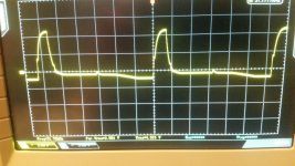
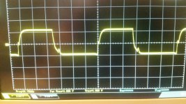
See attached pics, first pic is from the working punch at 14.4V
second pic also with 13.9VDC
third pic from the 225.2 and stays like this.
Or do they just have different regulation??
Thank you very much for your time.
i dont understand this part of your post 🙁
Best regards!
Andi
I tried out my new scope.
I have a working punch 160.2 which also uses TL494C.
The duty cycle changes from 13.9V to 14.5V DC supply voltage.
I measured on the gate leg of the PS-FET.
I tested the 225.2 and there is definitely no change in duty cycle when i change supply voltage. It only shuts down if voltage too low or high.
There is a slight change in amplitude but not in duty cycle.
See attached pics, first pic is from the working punch at 14.4V
second pic also with 13.9VDC
third pic from the 225.2 and stays like this.
Or do they just have different regulation??
Thank you very much for your time.
It's best to check the drive circuit with no PS FETs installed and using a small capacitor (0.01uF - 0.1uF) to load the FET location. The use of a loading capacitor significantly increases the chances of finding a weak drive signal.
i dont understand this part of your post 🙁
Best regards!
Andi
Attachments

Last edited:
Rockford tended to copy and paste circuits so the amp with no change in duty cycle may have regulation components from a higher powered amp.
What's the maximum rail voltage in the 225 just before it shuts down?
A drive circuit with no load may not show that it's weak. It may look like a perfect square wave but when the FETs are installed, the drive circuit may not be able to pull the gate voltage down, causing both banks of FETs to be on at the same time. This will cause excessive current draw and could cause the new FETs to be damaged.
Connecting a small capacitor across the gate and source pads loads the drive circuit and will tell you if the drive circuit is OK.
The maximum voltage before the amp shuts down is 48 volts.
Thank you for explaining this, i will test it tomorrow.
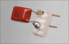
Next step is removing the 4 FETs and install 4 capacitors but i only have 0,15uF of type MKT1813.
Is that ok or should i order caps with smaller capacitance?
A drive circuit with no load may not show that it's weak. It may look like a perfect square wave but when the FETs are installed, the drive circuit may not be able to pull the gate voltage down, causing both banks of FETs to be on at the same time. This will cause excessive current draw and could cause the new FETs to be damaged.
Connecting a small capacitor across the gate and source pads loads the drive circuit and will tell you if the drive circuit is OK.
Thank you for explaining this, i will test it tomorrow.
Next step is removing the 4 FETs and install 4 capacitors but i only have 0,15uF of type MKT1813.
Is that ok or should i order caps with smaller capacitance?
The loading capacitor can be a higher value than suggested. What's important is that you know what to expect with the cap you chose to test with.
You only need one. Move it from location to location. I had mine on a header so it was easier to handle and the leads didn't constantly get bent out of shape.
If the amp isn't drawing excess current, you don't need to do this unless you just want to see the results.
You only need one. Move it from location to location. I had mine on a header so it was easier to handle and the leads didn't constantly get bent out of shape.
If the amp isn't drawing excess current, you don't need to do this unless you just want to see the results.
Attachments
Hi Perry!
Today i got time to measure further components and i found D5 was open. 🙂
I installed a new one.
Amp idles at around 0.9A but the heating of the FET is still there when amp pulls more than around 5A.
Is it possible that this diode caused damage to the FET?
D5 is around a half inch north-east of the IC LM339.
Maybe there is more damage but for today i have to stop.
I also noticed that every time i connect the remote, the amp pulls a lot of current ( more than 10amps) , the 10A supply shows a drop for a very short time, i think less than a half second. Is this the charging of the big caps?
BR
Andi
The inrush sounds like caps charging.
Does the amp work normally other than the heating of that FET?
What are you using to determine that it's hotter than the other transistors (FLIR, other IR, contact thermometer)?
Does the amp work normally other than the heating of that FET?
What are you using to determine that it's hotter than the other transistors (FLIR, other IR, contact thermometer)?
- Home
- General Interest
- Car Audio
- Rockford Fosgate Punch 225x2 - one Fet gets hot