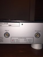
I have resurrected a Mark Levinson No. 30.5 digital processor / preamp from storage, along with its companion PLS-330 power supply. However, the cables that run between the 30.5 and the 330 are nowhere to be found. I would like to build some replacements, or have them built. There are three cables: two (i.e., left and right channel) "analog dc" cables; and one "digital dc" cable. I have included a photos of two of the ports on the back of the PLS-30 for reference. From the ports, and from photos I have seen of the cables online, it appears the cables use Lemo push pull connectors, 5-pin for the analog dc cables, and 2-pin for the digital dc cable. These connectors are available. I do not know the actual cable that was used. I have not been able to find any pinout info. I also have not been able to find schematics for the units.
Since these are basically just patch cables, it seems straight forward enough (isn't that where the problems often begin, "Well, it seemed simple enough...."). Just make sure the connectors on each end of the cable are wired the same. As for the actual cable, a starting question seems to be whether the cable should be shielded. I note that the Mark Levinson AC cord for the PLS-330 is shielded. That makes me think these should be shielded as well. Another question is whether the shield is connected to a pin on either of the cables. Thoughts? What else do I need to consider?
Thanks for your help.
Attachments
You could measure the power supply pins to verify the polarity and then trace the preamp connector to the pcb to make sure. Look for regulator inputs or something like that to verify which is positive.
I have some updated info to share. In addition to my post here, I also posted on a couple of other sites. No one had any conclusive info to share. I was finally able to connect with someone at Mark Levinson. They confirmed that these are simply pass through cables. So, in terms of pinout and wiring, it is simply a matter of making the same connections on each end, i.e., pin 1-1, 2-2, 3-3, etc. They also confirmed that these cables are shielded. However, they did not know whether the shielding was attached to the connectors, and if so how (e.g., on both ends, only on one end, etc.). Apparently, all of the people who worked on these units are long gone.
I am familiar with how shielded AC power cords are built. The shield is typically connected only on one end, the end that plugs into the wall. As I understand it, if you connect both ends the sound is degraded. Not sure if the same considerations apply here. It does not seem so, since there is no indication that there was a specific way to plug in these cords, i.e., either end could go into either component. That suggests that either both ends of the shield were attached, or neither end was attached. If anyone has any thoughts on that, let me know. Otherwise, I might start a separate post on how to build a shielded DC power cord.
I am familiar with how shielded AC power cords are built. The shield is typically connected only on one end, the end that plugs into the wall. As I understand it, if you connect both ends the sound is degraded. Not sure if the same considerations apply here. It does not seem so, since there is no indication that there was a specific way to plug in these cords, i.e., either end could go into either component. That suggests that either both ends of the shield were attached, or neither end was attached. If anyone has any thoughts on that, let me know. Otherwise, I might start a separate post on how to build a shielded DC power cord.
I did finally resolve this issue, so I wanted to report. Based upon the info from the Mark Levinson people, further consultation with others, and taking resistance and continuity readings from the various pins of the various ports, I decided to wire up the new cables with the shields connected at both ends. The units work/sound great, so I did not bother to try any other shielding configurations.
So, to review, I used Lemo connectors, size FGG.1B.305.CLAD52 for the five pin ports, and FGG.1B.302.CLAD52 for the two pin ports. "CLAD52" refers to the outer diameter of the cable, so you will need to check that one and adjust accordingly depending on what cable you use. I used shielded cable, with the shields connected to the housing of the connectors at both ends.
So, to review, I used Lemo connectors, size FGG.1B.305.CLAD52 for the five pin ports, and FGG.1B.302.CLAD52 for the two pin ports. "CLAD52" refers to the outer diameter of the cable, so you will need to check that one and adjust accordingly depending on what cable you use. I used shielded cable, with the shields connected to the housing of the connectors at both ends.